Type:Logic ICs
Condition:New
Model:V2.3
Contact form:Conversion type
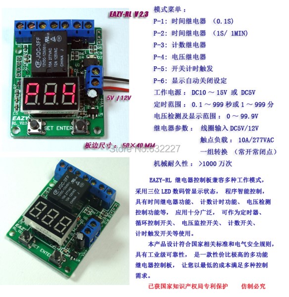
P-1: Time Relay (0.1 seconds to 99.9 seconds timer )
P-2: Time Relay ( 1 ~ 999 seconds or 1 to 999 minutes timer )
P-3: Counter / counter control relay
P-4: voltage relay / voltage detection control
P-5: switch timing trigger ( when the input level switch or timer to set the value of the trigger )
P-6: digital display automatically turns off the set ( minimum operating current 6mA / 12V)
Bulk purchase discount, a large quantity can not cut patterns , the default shipping is 12V version , operating supply DC10 ~ 15V, 5V power supply required version pleaseitem.taobao.com/item.htm?id=13331193647.
Please re- read the instructions before using the wiring operation !
Electronic version of the Manual Download:pan.baidu.com/s/1mTlDy
EAZY-RL V2.3 Controller User's Manual pan.baidu.com/s/1ssPYh
Timing range : 0.1 to 99.9 seconds , 1-999 seconds or 1-999 divided into three groups ( through the key settings).
Voltmeter display range :Default0-99.9V ( precision 0.1V) or 0-9.99V ( precision 0.01V), two hardware versions
Relay parameters:
Coil input DC5V / 12V ( corresponding to the power supply for DC 5V version / DC 12V version )
A set of conversion ( normally open normally closed )
Contact load : 10A / 277VAC
Contact resistance : 100m (1A-6VDC)
Mechanical Durability: > 10 million times
Electrical Durability: > 100,000 times (10A-250VAC)
Working temperature : -40 ~ 85
External signal input : Voltage (5-12V) or no voltage switch ( can be set to 9 debounce delay time )
Parameter can be powered down to save
Standby Current : 16mA / 12V, digital tube is closedMinimum 6mA / 12VAnd relay timely 45mA / 12V
If the power failure in either mode operation, the power again after the last state of the system will continue to run , parameter setting can be powered down to save , in either mode, press the ENTER key three seconds to return to the mode selected.
P-1, P-2, P-3 model, used as a timing relay, time relay , counting relay application video :( control 220V AC bulb )
http: // tudou.com/programs/view/tSX091IGb3I/
P-4 mode as a voltage relay demo video :
tudou.com/programs/view/yXPVSZ-X2bQ/
tudou.com/programs/view/D7zAOiEjvZI/
P-5 mode , switch timing trigger function demo video :
tudou.com/programs/view/y6PJVrgwhcg/
P-1: Time Relay Mode
Timing range : 0.1 to 99.9 seconds ; timer can be set two timer values T1 ( pull- time ), T2 ( release time ) , you can execute an infinite loop or a single countdown to execution.
P-2: Time Relay Mode
Timing range : 1-999 1-999 seconds or minutes, can be switched by key ; timer can be set two timer value T1 ( pull- time ), T2 ( release time ) , you can execute an infinite loop or a single countdown to execution.
Loop execution :
Time relay mode (P-2) , the user can set the relay pull- time T1 and release time T2, for example, is set for 3 seconds T1 , T2 for seven seconds , then relay run will first perform three seconds and then pull released for 7 seconds , and so on .
When you set the time value of T1 and T2 , the system can be powered down to save , automatically loaded the next time T1 after power and relay T1 T2 time and release time .
Single execution timing :
If only set T1 ( pull-in time ), T2 ( release time ) is 0, the relay timed run after T1 time to stop , no cycle operation , this time can be used as a timer , T1 time timing is complete, the relay is released , At this point press the ENTER key , the system re- T1 time to start timing .
If T1 ( pull- time ) is set to 0 , the relay has been in a released state ( does not start running normally closed switched on , normally open points off ) .
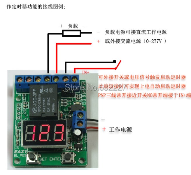
Via external switch / pulse input interface , you can control the start and stop time of the relay . In regular operation , the external switch input does not affect the regular operation , to be determined at the end , it will start the timer again when there is an external switch signal input.
Trigger the need for a rising edge of the start timer relay switch signal or an external pulse signal ( no-voltage switch is turned on, or voltage signal from low to high ) , if the input level remains unchanged ( or switch does not operate ) , does not trigger starts the timer .
P-3: Counting relay mode
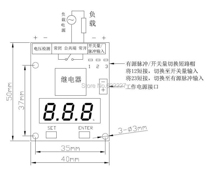
Can be used for external pulse or switch counterThe maximum value is 3999 , and set nine external signal debounce delay value , the maximum count frequency of 1M, counting signal connected to the right side on the map switching signal input terminal.Can be switched input signal ( active or passive pulse switch ) by shorting cap , external proximity switches , inductive switches, proximity switches can be used three-wire PNP normally open , with no need to switch shorted cap PNP proximity switch input ,The proximity switch is normally open relay output line access panel switch / pulse to the positive input terminal (IN +),Input voltage should be within 5-12V range , if the voltage exceeds 12V, the current limiting resistor required in series ( input current 10-30mA).
Due to mechanical switch contacts will have jitter may cause malfunction count , in order to avoid misuse switch jitter, press the ENTER key to select the input pulse to shake level can be set 9 , 10ms latency increases each level , showing "DL0 " to not delay ," DL9 " for the delay 90ms.
By counting mode can be set to the count value relay when external input count reaches the set value, the count value is automatically cleared weight parameters relay will press the "P-2 time relay mode" is set to perform ,The minimum time is 1 second timing ( For a minimum accuracy of 0.1 seconds timing may note message ) ,For example, you set at the time relay mode timing two seconds after release , then count the set value, the relay will pull two seconds and then release if time relay parameters are set to0When the count reaches the set value relay status will switch ( release becomes pull, pull becomes release ) .
P-4: Voltage RelayMode
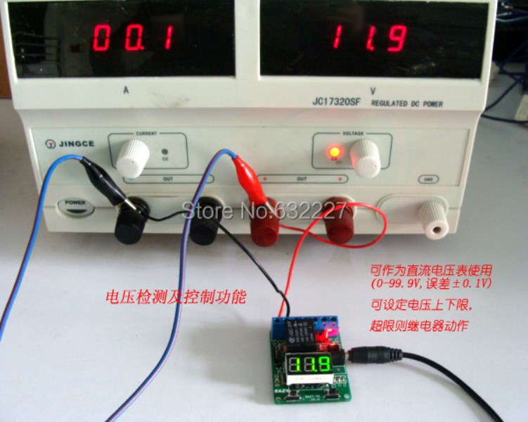
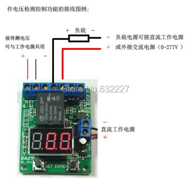
Use voltage detection control function can be set lower limits on the voltage , the voltage exceeds the upper limit of the relay contacts change from releasePickUntil the voltage is lower than the lower limit set only released again , this feature can be used for voltage monitoring temperature , other sensors and control , can also be used as a DC voltmeter , voltmeter display range :The default is0-99.9V, error of 0.1V,Required detection range0-9.99V, error of 0.01V relay board , please note instructions.
This mode can be set to the upper limit of the voltage detection control , and the lower limit voltage correction value (-0.5 ~ + 0.5V.
Voltage detection control mode demo video :
tudou.com/programs/view/yXPVSZ-X2bQ/
The factory default setting is the voltage exceeds the upper limit of the relay, the voltage drops below the lower limit of the relay is released , if the load connected to the relay normally open and common point , then switched load voltage exceeds the upper limit , below the lower limit of the load is disconnected, If you want the voltage exceeds the upper limit of the relay disconnects the load , then you can select one kind of in the following two methods to achieve:
A: The load connected to the normally closed relay and the common point , see the wiring diagram , so that the relay in the detection voltage exceeds the upper limit of pull, normally closed will be disconnected, the detected voltage is lower than the lower limit of the relay releases , often closing point will be connected ;
B: Press SET button for three seconds after releasing the P-4 mode, relay status negated , that the detected voltage exceeds the upper limit relay releases , the detected voltage is lower than the lower limit of the relay is energized .
Application examples :
Low battery alarm overvoltage control, automotive low-voltage detection and control , 12V battery discharge ( by detecting the battery voltage (10.5-14V), power control relay cement resistors in series , enabling automatic battery discharge function ) .
P-5: switch timing trigger ( 20,130,920 new features )
Can switch to external input or level timing ( access switch / pulse input terminal"IN") , Start the timer or the timing of when the relay switch setting . Timing of time and under the P-2 mode T1, T2 for the same group , 1-999 seconds or minutes adjustable .
If the external switch ( can also use three -wire PNP proximity switch normally open ) remains closed or level has been maintained up to the set value T1, the countdown is valid, if the external switch timer T1 is less than the set value is lost, the countdown stops wait to start again. For example : you set for 5 seconds T1 , T2 for 2 seconds , the external switch is pressed 5 seconds , the relay will pull two seconds and then disconnect , otherwise the relay does not pull . If set to 5 seconds T1 , T2 is 0, the external switch is pressed 5 seconds , the relay changes to pull the external switch is pressed 5 seconds again , the relay changes to the release .
Switch timing trigger function demo video :
tudou.com/programs/view/y6PJVrgwhcg/
P-6: digital closed automatically set
P-6 model is used to set the digital auto-off time ( 0 to 9 minutes , 0 is always on ) to reduce power controller , digital tube off when the minimum standby current of 6mA / 12V. Each mode can be running off in the digital tube display only closed, the relay is not affected. This mode function for 20,130,920 new post .
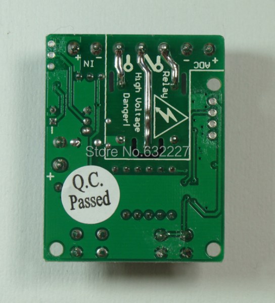
Relay wiring section marked with electrical safety warning for electrical isolation and grooving, high-current wires increases solder process .