Model Number:WP3084DAM
Type:Logic ICs
Condition:New
if want manual ,please contact us ,thank you.
First, product overview
l 8Road single ended analog input (DC type 0-10V), using an independent 12 bit industrial grade AD acquisition chip
l Using MODBUS RTU RS485 standard communication, can be configured with configuration software, PLC, industrial touch screen and other networking
l With communication status indicator
l Design of lightning protection and anti interference for communication circuit
l Signal acquisition and control can be widely used in industrial field equipment.
l Normal use of three years warranty
Two, the main parameters
l Analog inputpassageway8Single end of the road
l Analog input typeDC type 0-10V
l Analog input accuracy + 0.02V
l Operating temperature range -20 ~ 70
l External power supply 9V DC ~ 30V/2W
l Isolation protection 1500VDC
l Installation method standard DIN guide rail mounting or screw mounting
l Appearance size 125 * 73 * 35mm
Three, interface definition
| AVcc | External power input positive end |
| AGnd | External power input negative |
| VI_1+ | First channel analog input positive end |
| Gnd | Signal ground, then first analog inputs. |
| VI_2+ | Second channel analog input positive end |
| Gnd | Signal ground, then second analog inputs. |
| VI_3+ | Third channel analog input positive end |
| Gnd | Signal ground, then third analog inputs. |
| VI_4+ | Fourth channel analog input positive end |
| Gnd | Signal ground, then fourth analog inputs. |
| VI_5+ | Fifth channel analog input positive end |
| Gnd | Signal ground, then fifth analog inputs. |
| VI_6+ | Sixth channel analog input positive end |
| Gnd | Signal ground, then sixth analog inputs. |
| VI_7+ | Seventh channel analog input positive end |
| Gnd | Signal ground, then seventh analog inputs. |
| VI_8+ | Eighth channel analog input positive end |
| Gnd | Signal ground, then eighth analog inputs. |
| 485A | RS485Signal A+ |
| 485B | RS485Signal B- |
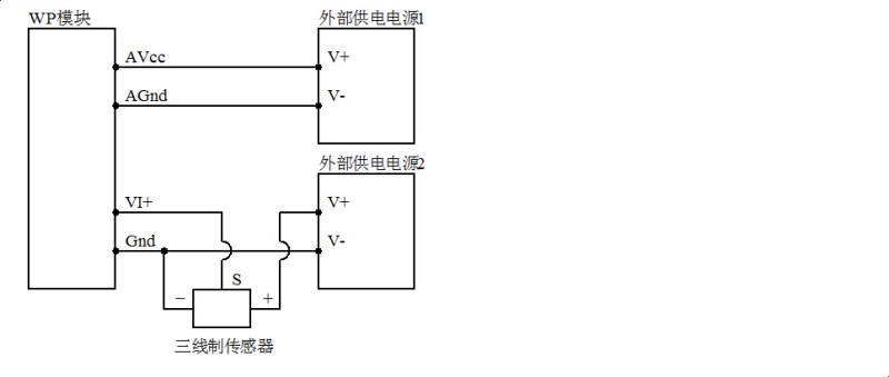
Four, analog input schematic
Five, communication instructions
1,Communication parameter description (ex factory value):9600, N, 8, 1
| parameter | Explain |
| 9600 | baud rate |
| (NNo verification | Check bit |
| 8 | Data bits |
| 1 | Stop bit |
2Analog input signal acquisition command:
Send: 01030000000844 0C (/16 system)
| data | byte | Data description | Remarks |
| 01 | 1 | Module address | Address range 01-FE |
| 03 | 1 | Function code | 03-Read register |
| 0000 | 2 | Register address (type 4x) | 0000-Analog input start register |
| 0008 | 2 | Read length | 0008-Read 8 registers |
| 440C | 2 | CRCCheck code | All data in front of the CRC check code |
Reception: 01031005 AF 0000000000000000000000000000C8 76 (case /16 system)
| data | byte | Data description | Remarks |
| 01 | 1 | Module address | Address range 01-FE |
| 03 | 1 | Function code | 03-Read register |
| 10 | 1 | Number of bytes | 10-Read 16 bytes in length |
| 05AF 0000 0000 0000 0000 0000 0000 0000 | 16 | Read data | 05AF-Read analog input channel 1 data 0000-Read analog input channel 2 data 0000-Read analog input channel 3 data 0000-Read analog input channel 4 data 0000-Read analog input channel 5 data 0000-Read analog input channel 6 data 0000-Read analog input channel 7 data 0000-Read analog input channel 8 data |
| C876 | 2 | CRCCheck code | All data in front of the CRC check code |
Receive instructions that analog input channel 1 voltage data for 05AF, converted to decimal number of 1455, substituted in the calculation formula v = (DATA*10) /4095= 1455*10 /4095 PRG 3.55V and other channel voltage data 0V
3,Module address setup command:
Send: 0006006400010804 (/16 system)
| data | byte | Data description | Remarks |
| 00 | 1 | Module address | 00-Group address |
| 06 | 1 | Function code | 06-Write single register |
| 0064 | 2 | Register address (type 4x) | 0064-Modify module address |
| 0001 | 2 | Write data | Setting module new address, range 0001-00FE |
| 0804 | 2 | CRCCheck code | All data in front of the CRC check code |
Receive: 0006006400010804 (/16 system)
The command said to a module issued a directive to the new address of the module is set to 01 and the setting can be lost to save power; the default module address is 01, when the need for networking a plurality of modules, the address of each module are set separately, because use the mailing, so setting requirements 485 network can only have a module, otherwise it will cause all the modules of 485 network address are set to the same address, please use caution the instruction; when the module receives the correct command, according to the order made corresponding action and response instruction is sent back to the host, said communication success
4Communication parameter setting command:
Send: 0106006500021814 (/16 system)

