Type:Logic ICs
Condition:New
First, the product overview
-6 single-ended analog input (DC type 0-10V)
-4 optically isolated digital inputs and 4 optically isolated digital outputs (NPN transistor open collector output)
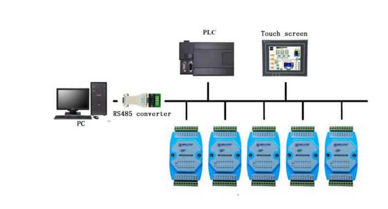
- RS485MODBUSRTU standard communication, can be networked with configuration software, PLC, industrial touch screen, etc.
-With communication and input and output status indicators
-Communication circuit adopts lightning protection and anti-interference design
- Widely used for signal acquisition and control of industrial field devices
Second, the main parameters
- Analog input channel 6 single-ended
- Analog input type DC type 0-10V
- Analog input accuracy ± 0.02V
- Digital input channel 4 channels (active low)
- Digital output channel 4 channels (NPN transistor open collector output, 500mA)
- Operating temperature range -20~70°C
-External power supply DC9N~30V/2W
-Isolation protection 1500VDC
- Mounting method standard DIN rail mounting or screw mounting
-Dimensions size 125×73×35mm
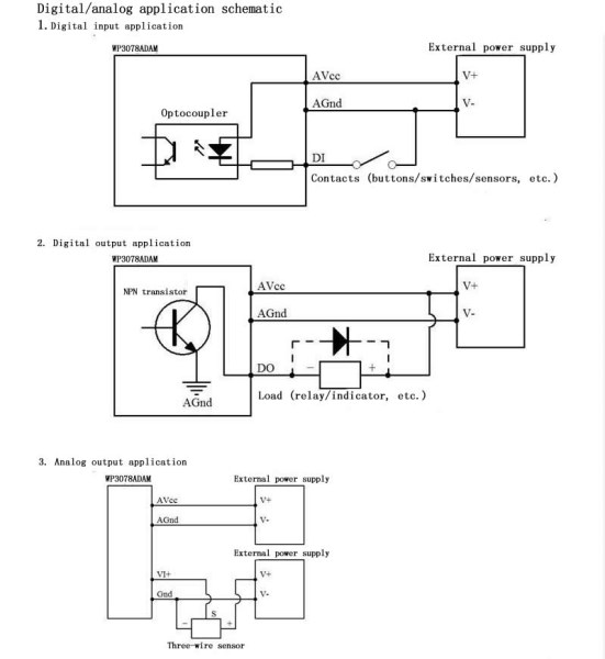
Third, the interface definition
AVcc: external power input positive terminal
AGnd: external power input negative terminal
VI_1+: the first positive input of the analog input
VI2+: 2nd analog input positive terminal
VI_3+: 3rd analog input positive terminal
VI_4+: 4th analog input positive terminal
VI_5+: 5th analog input positive terminal
VI_6+: 6th analog input positive terminal
Gnd: signal ground, connected to the negative end of the analog input
Gnd: signal ground, connected to the negative end of the analog input
DI_01: 1st digital input
DI_02: 2nd digital input
DI_03: 3rd digital input
DI_04: 4th digital input
D0_01: 1st digital output
DO_02: 2nd digital output
DO_03: 3rd digital output
DO04: 4th digital output
485A: RS485 signal A+
485B: RS485 signal B-
Fourth, the upper machine debugging instructions
This module provides a debugging software to implement the function debugging and parameter setting of the module. Please follow the steps below:
-Connecting computers and modules using RS485 converters
- Connect the 12V or 24V external power supply to the module and power it on. To avoid unnecessary damage, please check whether the positive and negative terminals of the power supply are connected correctly before powering on.
- Open the debugging software, select the corresponding module model, enter the function debugging or parameter setting interface
- Set the correct communication parameters and open the communication port
-·Select the appropriate settings, acquisition and control options
Fifth, RS485 networking diagram
Q1: What Is Your Product Warranty?
A: We Guarantee Our Product Is Fit For Its Normal User Purposes And Is Free From Defects In Materials Or Workmanship.
Q2: What Is Your Company Policy On Defective Goods?
A: Our Company Keep Items Quality For A Long Time. If There Are Any Defective Goods Due To
Production Defects Or Transportation Problem, Please Contact Us. Our Customer Service Team Will Provide Immediate Response To
Complaints. We Will Try Our Best To Give You A Good Resolve Way.
Q3: What Is Your MOQ (minimum Order Quantity)?
A: Generally Our Moq Is No Limited. Please Have More Discussion With Us If Your Combination Of Models Is Complicated.
Q4:how About Getting Samples From You?
A: We Will Send You The Samples After We Receive The Payment For Samples. The Buyer Shall Afford The Shipping Cost. Please Have A
Confirm With Us Which Shipping Way Do You Want.
Q5:about The Shipment: What Type Of Shipment Will You Use?
A: We Usually Ship The Products By Express(delivery It To Your Door) Or By Air Freight To Your Nearest Airport, Shipping Days:3-7
Working Days Depend On Destination;if The Order Quantity Is Large, We May Ship By Sea Container And The Best Ship Way Is By Sea,
Shipping Days: Over 20 Working Days Depend On Destination Port.
Q6:what Packing Do You Use?
A: Neutral Package With Airbag Or Customized Package.
Q7:how Much Are The Shipping Cost?
A:shipping Cost Is Charged By The Package's Weight And Related To The Shipping Methods You Choose And Your Destination.
Q8:how To Order?
Step1.Click (Add to Cart) Buy Directly On The Product Page, Or Add To Shopping Cart And Settle Together, Pay With Paypal,
Need your information, such as full name,country, city, detail address, post code, tax number ...
Step2. We Will Delivery by EMS POST, FedEx or DHL Within
3-5 Working Days After Payment Confirmed.
Setp3. Confirm Us Receipt of Products.

