Condition:New
Type:Logic ICs
Model Number:MB4AI4AO
Operating Temperature:-10 to +55
Supply Voltage:10V-30V
Dissipation Power:4W
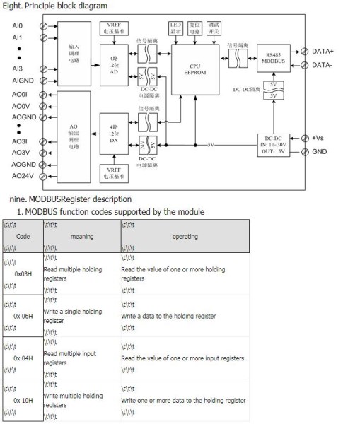
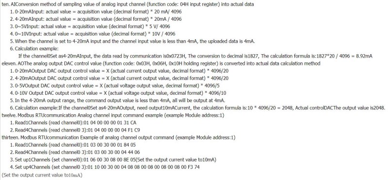
4 analog input and 4 analog output module, which can gather 4 road 0-20mA, 4-20mA, 0-5V, 0-10V four kinds of input signal and control 4 0-20mA, 4-20mA, 0-5V, 0-10V four kinds of output signal; analog signal data collected by 4AI, by isolating the RS485 interface output through the analog output isolation from the RS485 interface can control 4AO
The first chapter product introduction
Please choose0-20MA/4-20MA/0-5V/0-10V,default is 0-10V
A.Summary
MB4AI4AO 4Analog input and 4 analog output module, which can gather 4 road 0-20mA, 4-20mA, 0-5V, 0-10Vfour analog input signal and 4 0-20mA, 4-20mA, 0-5V, 0-10V four kinds of analog signal output; analog signal data collected by 4AI, by isolating the RS48Fiveinterface output control 4AO by isolating the RS485 interface data output module; using Modbus-RTU communication, can be directly adapted to PLC, DCS and various domestic configuration software etc..
Signal acquisition, signal output, power supply, RS485 communication electrical signals isolated from each other, the effective suppression of all kinds of serial mode and common mode interference, to ensure the accuracy of the data, but also to ensure the reliability of the module.
Two.Characteristic
OneUsing standard Modbus-RTU protocol.
2.According to their own needs to set the input signal type of each channel.
ThreeAOAnalog output mode
Module function mode | Functional characteristics |
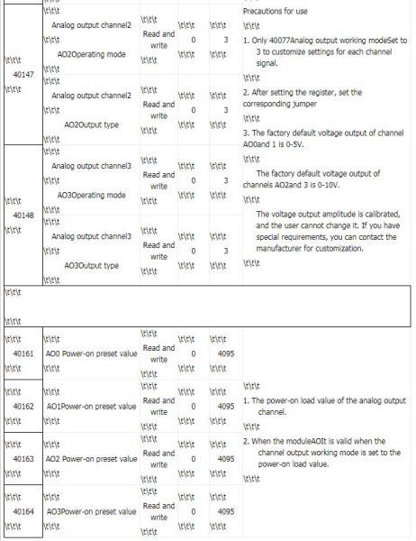
Load preset mode | 1.Analog outputAOThe initial value can be set to load a value, the default is to load0Value. 2.When the module is powered on, the analog outputAOLoad [AOInitial value. |
Electric load off value mode | 1.The power supply of the uninterrupted monitoring module, when the module is detected, the current is recorded and stored.AOChannel output value. 2.When the module is powered up again, the analog outputAOLoad the value before power down. |
Isolator mode (safety gate operating mode) | OneAnalog outputAO0The output size is determined by the value of the AI0. TwoAO0The output value changes with the value of AI0, which is not controlled by the computer to change the output. ThreeSeveral other channels and so on |
4.Security: signal acquisition, signal output, power supply, RS485 communication electrical signals isolated from each other.
5.Communication protection: RS485 communication signal output interface using overvoltage and over current dual protection.
SixThe input signal type, the output signal type, and the communication format can be set through the software.
7.Power polarity protection.
Three.Technical index
project | parameter |
AI Signal input | 1Input channel: 4 channel isolated analog acquisition 2Input signal type: 0~20mA, 4~20mA, 0~5V, 0~10Vfour analog signal 3Sampling rate: 4 channels per 5mS acquisition time 4Resolution: 12 bit 5Precision: voltage 0.2% current 0.3% SixIsolated voltage protection: 1500V |
AO signal output | 1Output channel: 4 channel isolated analog output 2Output signal type:0~20mA4~20mA, 0~5V, 0~10V four analog signal 3Sampling rate: 4 channel 5mS can be updated once 4Resolution: 12 bit 5Acquisition precision: voltage 0.2% current 0.3% SixIsolated voltage protection: 1500V |
RS485 Communication output | 1Communication protocol: MODBUS-RTU 2Interface type: isolated RS485 communication, the output of the interface using the overvoltage and overcurrent protection 3Baud rate: 1200BPS, 2400bps., 4800bps, 9600bps, 19200bps 4Check bit: no parity check, parity check 5. setting: module address, baud rate, parity bits can be set by software SixIsolated voltage protection: 1500V |
Module size | A.Separate module size: 104mm*72mm*26mm B.With terminal and guide rail box size: 124mm*72mm*45mm |
Installation method | Standard DIN guide rail installation(35mm guide rail or high and low track) |
work environment | Temperature: -10 ~ +55 temperature humidity: 35~85%(not dew) |
Working power supply | 1Power supply voltage: 10V~30V wide range of power supply, with the power supply polarity protection 2Power consumption: less than 4W |
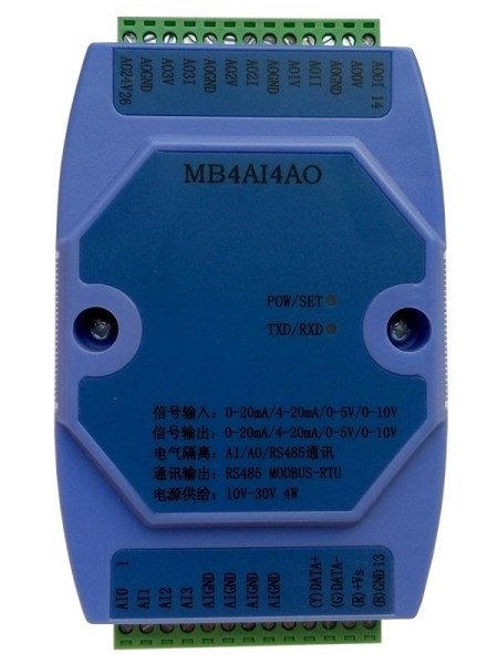
Four.Product appearance and external wiring diagram
Five.Module indicator lamp and switch function specification
1.POW/SET;Module working status indication
A.Green light: the module works in the running state. B. red light: the module has the configuration parameters have been written, need to re power up.
2.TXD/RXD:Communication status indication
A.The green light flashes: the communication receives the data B. red light flashes: the module is sending data
C.The green light is always on: DATA+ and DATA- on the communication line RS485 line is connected to the reverse or the connection is broken.
ThreeModule right reset switch
A.When the communication parameters (module address, baud rate, parity bit) do not know or communication parameter misspecification, and can not establish contact module communication, the solution is to reset the communication parameters; we use the clip to hold the reset switch is not open, 5 seconds after the [POW/SET] module of the red indicator lights, release the reset switch, the communication the parameters have been reset, as long as the power supply module after the restart time, the communication parameters of the module has been reset.
B.Communication parameters after reset: Address: 1, baud rate: 9600bps, parity: No.
Six.Typical application wiring diagram

Seven.Terminal definition
terminal | Name | Explain | | terminal | Name | Explain |
1 | AI0 | Analog input 0 channel positive end | 14 | A00I | Analog channel 0 current output |
2 | AI1 | Analog input 1 channel positive end | 15 | A00V | Analog channel 0 voltage output |
3 | AI2 | Analog input 2 channel positive end | 16 | AOGND | Analog channel 0 output negative terminal |
4 | AI3 | Analog input 3 channel positive end | 17 | A01I | Analog channel 1 current output |
5 | AIGND | Analog input negative | 18 | A01V | Analog channel 1 voltage output |
6 | AIGND | Analog input negative | 19 | AOGND | Analog channel 1 output negative terminal |
7 | AIGND | Analog input negative | 20 | A02I | Analog channel 2 current output |
8 | AIGND | Analog input negative | 21 | A02V | Analog channel 2 voltage output |
9 | NC | empty | 22 | AOGND | Analog channel 2 output negative terminal |
10 | DATA+ | RS485Communication + | 23 | A03I | Analog channel 3 current output |
11 | DATA- | RS485Communication - | | 24 | A03V | Analog channel 3 voltage output |
12 | +Vs | Power input + | | 25 | AOGND | The analog channel 3 outputs the negative end |
13
|
GND
|
power input-
| |
26
|
AO24V
|
Analog output 24V power supply positive terminal |