Type:Drive IC
Supply Voltage:DC8-30V
Operating Temperature:-35 to +50
Model Number:YC102
Condition:New
Model:YC102
Decoration and construction contents:Installation engineering
Can choose:10 way output 20mA(default);10 way output 10V;10 way output 5V.Other output types are required. Please contact the seller.
1.Summary
Be based onRS485 Interface,Modbus Analog output control module of the protocol. Each channel uses an independent 1Twobit DA.
quarantineRS485Interface supportModbus-RTU Agreement.
Power source: DC8-30V.
Current output type:0-20MA (21mA MAX)The output voltage is the same as the supply voltage, Load resistance 0 euro to 800 ohm.
Voltage output type:0-5V,0-10V Output limited current short circuit protection, the output current is not more than 5mA.
High accuracy: voltage type, output accuracy 2/1000, current type accuracy 7/1000.
Outline size:88*72*59
Operating temperature:-35+ 50.
Use standard 35mm Installation way of guide rail.
Field of application: analog output control, automatic control.
2.Product models, pictures, and interfaces
The interface definitions are illustrated with labels
A:RS485 serial communication A
B:RS485 serial communication B
Power V+: DC power positive
Power V-: DC power negative
AOx: analog output
AGND: analog output negative common terminal
3 register information table
3.1Function code03H(read),06H(write)
Parameter setting register information table 10H-15HPermanent preservation;16H-1FHPower loss is lost when power is on0.
When the module is powered on, the value is0. Therefore, the power must be written to the value of the output.
| Word address | byte position | describe | Parameter description | attribute |
| 10H | low8position | Communication configuration Initial value:00 | BIT<7> Parameter protection function= 0Close = 1open See Notes BIT<6:5> Retain BIT<4:3>00=No check01=Even check10=Odd check11=Odd check) BIT<2:0>000=9600, 001=1200, 010=2400, 011=4800, 100=9600 101=14400 110=19200Other combinations are not defined, in accordance with9600Handle | RW |
| high8position | Postal address Initial value:01 | Set range=1reachTwo hundred and fifty address0For the broadcast address (if the communication program sets the value of0Equal to1) | RW |
| 11H | | Retain | | RW |
| 12H | | Retain | | RW |
| | Retain | RW |
| 13H | | Retain | RW |
| 14H | | Retain | RW |
| 15H | | Retain | RW |
| 16H | | No.1Road analog output value | Voltage or current output value,2Unsigned integer of bytes, the unit of value is:UA,MV. When the module is powered on, the value is0. Therefore, the power must be written to the value of the output. For example, to set the output20mA20mA=20000uAConvert to16Hexadecimal4E20H | RW |
| 17H | | No.2Road analog output value | RW |
| 18H | | No.3Road analog output value | RW |
| 19H | | No.4Road analog output value | RW |
| 1AH | | No.5Road analog output value | RW |
| 1BH | | No.6Road analog output value | RW |
| 1CH | | No.7Road analog output value | RW |
| 1DH | | No.8Road analog output value | RW |
| 1EH | | No.9Road analog output value | RW |
| 1FH | | No.10Road analog output value | RW |
3.2 Function code10H(write register)
16H-1FHRegister supportMODBUSThe10HCommand. The significance of this function lies in:
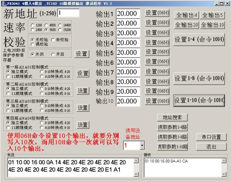
Use06HCommand setting10Two outputs are written separately10Time and use10HThe command can be written at a time10Two outputs.
4 module application technology
4.1 MODBUSagreed interpretation
Please refer toV2.4Single-phase three-phaseLEDLCDGeneral description of instrumentMODBUSIntroduction.
You can use the test tools we provide to view the data collected. Following chart.
Analog output test software:
AO1-AO4andPD3041-4AI4AOSame address.