Brand Name:icchipcn.com
Condition:New
Type:Logic ICs
Chapter 1 Product Introduction
1. Overview
MB10DI18RO 10-channel switch input quantity acquisition and 8-channel relay output module, can collect 10-channel dry contact or wet node signal (active or passive input); as dry contact input or sensor (NPN or PNP) input, you can set jumper common Positive or common negative input; as an active input, the polarity is automatically converted without jumper switching; the 4-way relay can be controlled through the MODBUS bus; the module adopts Modbus-RTU communication, which can be directly adapted to PLC, DCS and various domestic configuration software, etc.
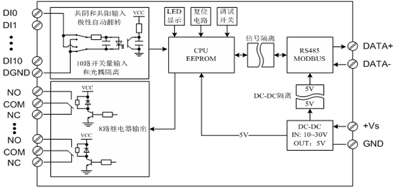
Switch input and relay output, power input, and RS485 communication electrical signals are isolated from each other, effectively suppressing all kinds of series-mode and common-mode interference, and ensuring the module works reliably.
2. Features
Using Modbus-RTU protocol, it can be directly adapted to PLC, DCS and various domestic configuration software.
Signal acquisition, relay output, power supply, and RS485 communication electrical signals are isolated from each other.
RS485 communication signal output interface adopts overvoltage and overcurrent double protection.
Input signal type and communication format can be set by software.
Power polarity protection.
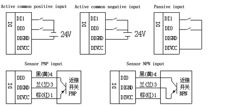
Flexible Open Input Signal Settings
When set to active input, the open input signal can be a common anode input or a common cathode input at the same time.
When set to dry contact input, just short the DI input to DIVCC.
3. Technical indicators
Item | Parameter |
Signal input | 1. Input channel: 10-way dry contact or wet node
switch input 2. Signal type: common cathode or common anode
input polarity automatic identification 3. Signal level: high level (10V ~ 30V) low level
(0V ~ 3V) 4. Sampling rate: 1000HZ 5. Isolation voltage protection: 1000V |
Signal output | 1. Output channel: 8-way normally open relay
output 2. Load capacity: resistive load 250V/3A
inductive load 250V/1A 3. Isolation voltage protection: 1000V |
Communication
output | 1. Communication protocol: MODBUS-RTU 2. Interface type: isolated RS485 communication,
output interface adopts overvoltage and overcurrent double protection 3. Baud rate: 1200bps, 2400bps, 4800bps, 9600bps,
19200bps. 38400bps, 57600bps, 115200bps 4. Check digit: no parity, even parity, odd
parity 5. Setting method: module address, baud rate,
parity bit are set by software 6. Communication distance: @9600bps 1200 meters 7. Electrical isolation protection: 1000V |
Module size | 115mm*90mm*40mm |
Install
method | 1. Rail installation: standard 35mm DIN rail
installation 2. Screw fixing (length and width): 105mm*70mm |
Working
environment | Temperature: -20 ~ +60℃ Humidity: 15~85% (non-condensing) |
Working power | 1. Power supply voltage: 10V~30V wide range power
supply, with power supply polarity protection 2. Power consumption: less than 4W |
Module weight | 220g |
4. Product appearance? ?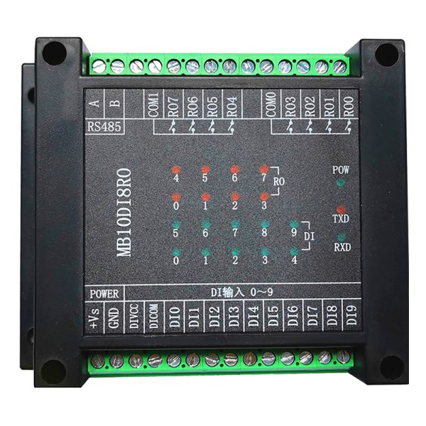
5. Module peripheral wiring diagram
1. Switch input wiring instructions
?2.Relay output connection (normally open)

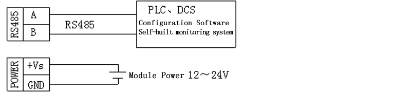
3. Connection of communication and power
6.Module indicator light and switch function description
1.POW/SET; module working status indication
A. The green light is on: the module is
working in the running state.
2.TXD/RXD: communication status indication
A. The green light is flashing: the
communication has received data
B. The red light is flashing: the module is
sending data
C.
The green light is always on: the communication RS485 lines connected to DATA+
and DATA- are reversed or the connection is broken.
3. The purpose of the reset switch on the
left side of the module
A.
When the communication parameters (module address, baud rate, check digit) are
unknown or the communication parameters are set incorrectly, and the
communication with the module cannot be established, the solution is to reset
the communication parameters; find the reset switch on the right side of the
module, and use Press and hold the module switch with a paper clip, and after 5
seconds, the green indicator [POW] of the module will turn off and turn on
again. At this time, release the reset switch, and the communication parameters
have been reset. At this time, the communication parameters of the module have
been reset.
B.
Communication parameters after reset: address: 1, baud rate: 9600bps, parity
bit: none.
7.Schematic block diagram
Chapter2 Modbus register and communication protocol description
1.MODBUS function codes supported by the module
Register type | Function code | Function code
description |
coil register | 0x01H | Read one or more coil registers |
0x05H | write a coil register |
0x0FH | write one or more coil registers |
Open input
register | 0x02H | Read one or more binary registers |
input
register | 0x04H | Read one or more input registers |
holding
register | 0x03H | Read one or more holding registers |
0x06H | Write a data to the holding register |
0x10H | Write one or more data to holding registers |
2. Register Definition Description
1. Coil register (function code can be used: 0x01H, 0x05H, 0x0FH) address
Address | Parameter | Read/write | Minimum | Maximum | Explain |
00001 | RO0 | Read/write | 0 | 1 | Relay output 0 |
00002 | RO1 | Read/write | 0 | 1 | Relay output 1 |
00003 | RO2 | Read/write | 0 | 1 | Relay output 2 |
00004 | RO3 | Read/write | 0 | 1 | Relay output 3 |
00005 | RO4 | Read/write | 0 | 1 | Relay output 4 |
00006 | RO5 | Read/write | 0 | 1 | Relay output 5 |
00007 | RO6 | Read/write | 0 | 1 | Relay output 6 |
00008 | RO7 | Read/write | 0 | 1 | Relay output 7 |
?2.Discrete input register (function code can be used: 0x02H)
Address | Parameter | Read/write | Minimum | Minimum | Explain |
10001 | DI0 | Read only | 0 | 1 | Switch input
channel 0 |
10002 | DI1 | Read only | 0 | 1 | Switch input
channel 1 |
10003 | DI2 | Read only | 0 | 1 | Switch input
channel 2 |
10004 | DI3 | Read only | 0 | 1 | Switch input
channel 3 |
10005 | DI4 | Read only | 0 | 1 | Switch input
channel 4 |
10006 | DI5 | Read only | 0 | 1 | Switch input
channel 5 |
10007 | DI6 | Read only | 0 | 1 | Switch input
channel 6 |
10008 | DI7 | Read only | 0 | 1 | Switch input
channel 7 |
10009 | DI8 | Read only | 0 | 1 | Switch input
channel 8 |
10010 | DI9 | Read only | 0 | 1 | Switch input
channel 9 |
???3.Holding register (function codes can be used: 0x03H, 0x06H, 0x10H)
Address | Parameter | Read/write | Minimum | Minimum | Explain |
40065 | Device type | Read only | 0 | 256 | 14?(MB10DI4RO module) |
40066 | Device state | Read only | 0 | 0x0101 | Bit4: Reset
button state Bit0: Module
reset request flag |
40067 | Module voltage | Read only | 0 | 300 | 0.0-29.9V |
40069 | Product version | Read only | 0 | 65535 | Hardware
version (upper 8 bits) + software version (lower 8 bits) |
40070 | production information | Read only | 0 | 65535 | Year (upper 8
digits) + lot number (lower 8 digits) |
40071 | Module address | Read/write | 1 | 247 | 1(Default) |
40072 | Baud rate | Read/write | 0 | 7 | 0(1200)
1(2400) 2(4800) 3(9600)? Default 4(19200) 5(38400) 6(57600) 7(115200) |
40073 | Check Digit | Read/write | 0 | 2 | 0 (no
parity.) Default 1 (even parity) 2 (odd parity) |

