Brand Name:icchipcn.com
Condition:New
Type:Logic ICs
Model:PD305X
Color Classification:12 single-ended input circuit current 20mA 12 single-ended input volta
Renovation and construction content:Installation Engineering
12 road single-ended input circuit current 20mA ;
12 road single-ended input voltages 30V;
8 road current 20mA + 4 voltage 30V ;
12 road single-ended inputs 0-5V ;
6 road differential inputs 20mA ;
6 road differential inputs 5V 18bit 250mV (-120mV to 250mV).
please note what you choose above ,thenk you.
1.Outline
Main features
1: Isolated RS485interface , voltage Modbus protocol , the current analog acquisition module . Networking can be carried out with the PLC, configuration software, text display , etc.
It can be widely used in industrial field signal control equipment .
2: Wide operating voltage :DC8V-30VPower reverse does not work. Using original MC34063A 38V switching power supply can work within , the power consumption is less than0.5W.
3: Working temperature :-35 ~+50.
4: On-chip voltage referenceVREF = 0.256V
1)Accuracy:0.256V±0.05%
2) Drift :15 ppm /°C
Low reference voltage means can measure very small signal , such as :75mVDC shunt , the bridge output. Thus eliminates the need for a precision amplifier .
5: Multiple data formats output:
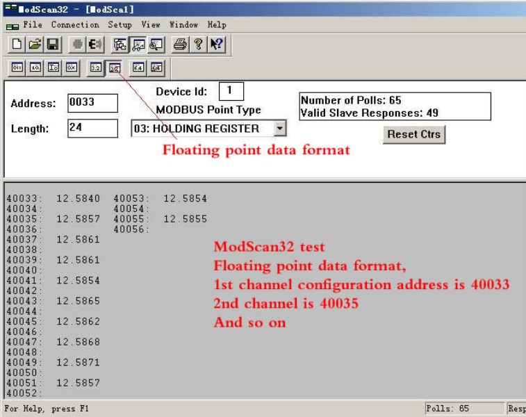
1)32PositionStandardIEEE-754Floating-point format , without any conversion data is analog input values.
2)16Bit unsigned integer output data unitsμA,mV.
3)32-Bit digital output code samples , users can eachLSBRepresent equivalent calculation input.
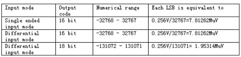
6: Sampling median16Position,18Position,Twenty fourBit high resolution.
1 )Single-ended input type modulesHigh speed16PositionADSampler, the range of values-32768-32767.
2)Differential input type modulesHigh speed18PositionADSampler, the range of values-131072 --131071.
Again :Using three standard 16 -speed differential AD, each piece is responsible for four channel sampling , so you can measure the negative input. ( For 18 AD please specify)
0-20mA this specification , can measure -15mA to 0 to + 20mA,
0-30V this specification , can measure the -20V to + 30V. ( For other voltages , please explain , for example, plus or minus Twenty fourV input. )
We provide the register type , floating point , signed integer , the digital output is signed .
Each current inputs have protection , even if access 24V without damage.
7: Multiple access methods
1) Single-ended input
2) Differential input
8: no interference phenomena between channels . Even if the input signal exceeds the range many times , but also no phase interference.
Some manufacturers of the products when the input exceeds the range , it will interfere with other channels , our products will not happen.
9: Installation: Standard35mmRail mounting.
By way of explanation of a phenomenon common to other module manufacturers :
Q: Why , when a voltage signal acquisition , then all the way to the signal , the other channel has value ?
Manufacturers Answer : This is a phenomenon that all manufacturers are present ( due to voltage signal interference ability is poor ) . To receive a signal all the way , if there is no other path to ground , then still in limbo , then the value of the other channels close to the value displayed on a channel.
The answer , and the nature of the fundamental reasons vain side . The fundamental reason is :
AD chip module uses a switch between multiple channels . If the reference voltage if AD is 2.5V, 4.096V, even 5V,
Then the full-scale input to the AD will be sampled voltage VREF voltage. High voltage can cause a problem , is to simulate
Switch ( switch channels ) channel interference occurs , the more severe the higher input , even when the supply voltage exceeds the device especially when the voltage reaches .
There are examples of the most common channel isolation is this: we used two-channel amplifier, if the chip is in a two -channel , then
In a channel plus music signal , another channel without signal , the other channel will be minimal music. Theoretically should not have .
That is the problem of channel separation .
Therefore, the most fundamental way is to use a one -channel AD.
Our module , due to VREF = 0.256V, compared to VREF = 2.5V ..... , in order to achieve the same interference , it would have the input signal
Up to : 2.5V / 0.256V = 10 times . In other words , you need to add 10 times the range of the signal generated by the interference , it is equivalent to other manufacturers to join one times the range of the degree of interference.
This situation is unlikely to occur .
3Module interface
Interface defined label instructions
?
Signal words are defined as follows :
(Vin): DC power positive input
(GND): DC power supply common.
(A):RS485Serial Communications A.
(B):RS485 Serial CommunicationsB
IN: Analog Input
IN +,IN-: Differential input positive terminal , the negative terminal
?
4 internal interface structure
BecauseVREF = 0.256V, So the input toADThe full-scale voltage chip is0.256V, Appropriate selection resistor network , can ensure a sufficiently high resolution .
Single-ended input structure | 20mASingle-ended input | 30VSingle-ended input |

| R1 = 0 R2 = 12Europe Can be measured so the actual 0.256V / 12Europe= 21.33mA
| R2 = 3.24K R1 = 390K Can be measured so the actual 0.256V * 121.37 = 31V
|
6 register information table
6.1Function code03H( Read)06H( Write )
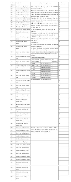
Parameter setting register information table
Word Address | Byte Location | Description | Parameter Description | Property
|
10H | Low8Position | Communication Configuration Initial value:00 | BIT<7:5> Retention BIT<4:3>00 =No parity01 =Even parity10 =Odd parity (11 =Odd parity ) BIT<2:0>000 = 9,600,001 = 1,200,010 = 2,400,011 = 4,800,100 = 9600 101 = 14400110 = 19200Other combinations are not defined , in accordance with9600Deal with | RW |
High8Position | Mailing Address Initial value:01 | Setpoint range= 1To250 Address0 Broadcast address ( If the value set for the communication program0Equivalent to1) | RW |
11H | Low8Position | Round objects enable significant Initial value:255 | Retention | RW |
High8Position | Round display switching interval Initial value:05 | Setpoint range= 0To255( Sec ) If set to00H, Then with01HEquivalent . | RW |
?
?
6.2Function code03H( Reading )
Data register information table
Device output code to the input signal voltage conversion chip reference voltage VREF=0.256V
Modscan32 test floating point register
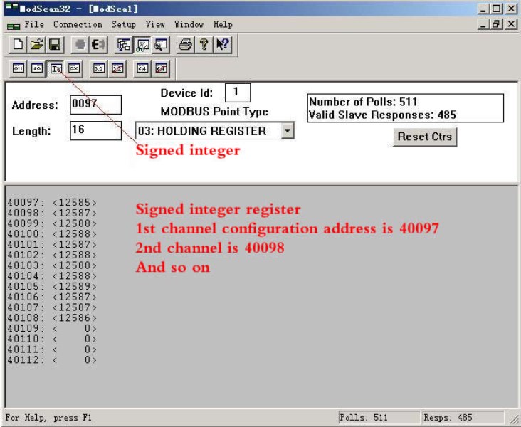
Modscan32 Test Signed Integer Register
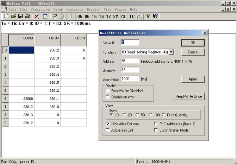
Modbus pool test Floating point register
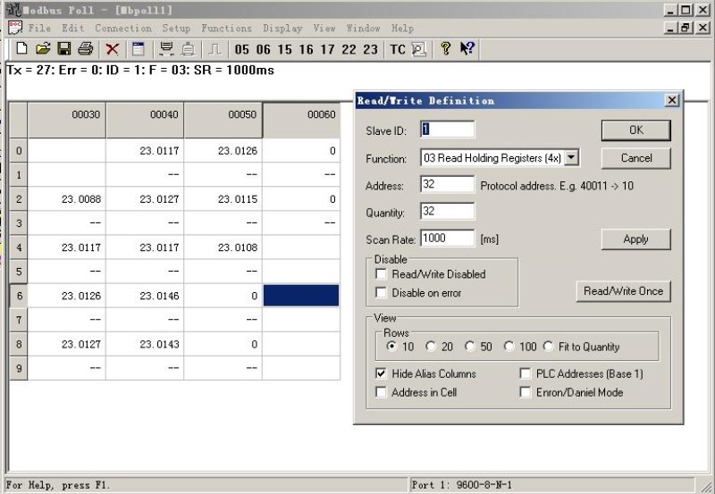
Modbuss pool test Signed integer registers