Condition:New
Type:Logic ICs
Model Number:PD3058E
1.Summary
Main characteristics
1RS485 isolation interface, Modbus protocol voltage, current analog acquisition module. With PLC, configuration software, text display, etc.,
The utility model can be widely used for signal control of industrial field equipment.
2Wide operating voltage:DC8V-30VThe power supply is not working. Using original MC34063A switch power supply 38V can work normally,
Measured 30V power consumption 9mA, 24V power consumption 12mA, 12V power consumption 22mA, 8V power consumption 32mA.
3Working temperature:-35C ~+50C.
4On chip reference voltageVREF=0.256V
1Precision):0.256V.0.05%
2Drift:15 ppm/DEGC
A low reference voltage means that a very small signal can be measured directly, such as:75MVDC shunt, bridge output, etc..A precision amplifier can be omitted.
5Multiple data format output:
1)32positionStandardIEEE-754Floating point format, the data without any conversion, analog input value.
2)16Bit unsigned integer outputMuA,MV.
3)32Bit sampler digital output code, the user can pass eachLSBEquivalent calculation input.
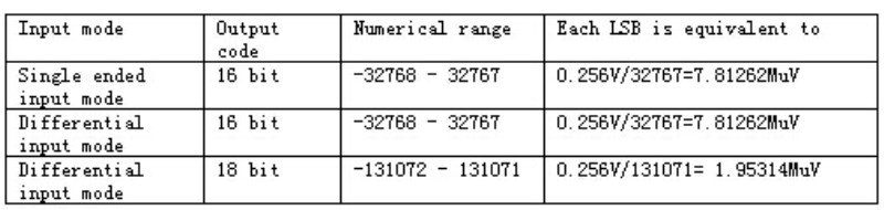
6The sample number is16A,18High resolution.
1) Single ended input typehigh speed16positionADSampler, numerical range-32768-32767.
2) Differential input typehigh speed18positionADSampler, numerical range-13107Two- 131071.
Emphasize again: standard use3Chip speed16Phase differenceADEach piece is responsible for4The channels are sampled so that negative values can be measured.(if need18positionADPlease explain)
0-20mAThis specification can be measured completely-15mAreach0reach+20mA,
0-30VThis specification can be measured completely-20Vreach+30V.(For other voltages, please specify, for example, positive and negative24VInput.)
We provide register types, floating point numbers, signed integers, and digital output.
Each current input interface is protected even if access24VNot damage.
7There is no mutual interference between channels. Even if the input signal is many times more than the range, there is no interference phenomenon.
Some manufacturers of products in the input over the range, it will interfere with other channels, our products will not be the case.
8: installation: Standard35mmRail installation.
Explain the common phenomenon of the modules of other manufacturers:
Q: why, when the voltage signal is collected, the signal is connected to the other channel
Manufacturers answer: This is the phenomenon of all manufacturers (due to poor anti-interference voltage signal). If the other channel is not grounded, it is in a suspended state. The value of the other channel is displayed as the value of the previous channel.
This answer, and the essence of the reasons for the edge. The root cause lies in:
Module use1individualADChip switching a plurality of channels, ifADIf the reference voltage is2.5V,4.096VAnd even5V,
Then enterADThe full sample voltage will beVREFVoltage. Too high a voltage can cause a problem
switch(Switching channel)Channel interference occurs, the higher the input, especially when the voltage reaches or exceeds the supply voltage of the device.
One of the most common examples of channel isolation is the use of a dual channel amplifier, which is used in a single chip2One track, then
In one track with a music signal, and the other without any signal, then the other channel will be a small musical sound. Theoretically should not have.
This is the problem of channel isolation.
So the most fundamental way is to use a single channelAD.
Our modules due toVREF=0.256V, compared toVREF=2.5V...In order to achieve the same interference, it is necessary to input the signal
Raise to:2.5V/0.256V=10Times. That is, the need to join10Times the range of the signal, the interference generated by the equivalent of other manufacturers to join1Degree of interference.
This is not going to happen.
9: The module can be equipped with a 128*64 OLED display module, which displays the current channel values in four screens.Refresh 2 times per second. The first line of the screen displays the current communication parameters, address, baud rate, parity, and so on.When you need to display the function shot, follow the classification with the display, which is the classification with OLED.?
10:20mA acquisition, you can choose 0-20mA mode and 4-20mA mode, the difference is:0-20mA mode: It can measure 0.000mA-20.000mA, and the read value is the same as the input actual current.Enter 1.000mA, the read floating point number is 1.0000, and the read integer is 1000.Enter 4.000mA, the read floating point number is 4.000, and the read integer is 4000.Input 20.000mA, read floating point number is 20.0000, read integer is 200004-20mA mode: It can measure 4.000mA-20.000mA, and the read value is different from the input current.The input is less than 4.000mA and the value read is 0.Enter 4.000mA, read floating point number is 0.0000, read integer is 0000Input 12.000mA, read floating point number is 10.0000, read integer is 10000Input 20.000mA, read floating point number is 20.0000, read integer is 20000Therefore, if you want to choose the 4-20mA mode, you should select the category "4-20mA mode" when shooting.The "8-way 4-20mA mode +4 voltage" voltage specification should be noted.??
For example: the transmitter output 4-20mA corresponds to 0-150 degrees, module selectionOne: module selects 20mA specification, then 4mA sample value 4.000 (integer 4000) corresponds to 0 degree, 20mAThe sample value of 20.0000 (integer 20000) corresponds to 150 degrees.Two: module selects 4-20mA specification, then 4mA sample value 0.0000 (integer 0) corresponds to 0 degree, 20mA samplingThe value 20.0000 (integer 20000) corresponds to 150 degrees.?
2 Product type classification and image
Commonly used models are as follows:
PD3058-12I2Zero12Single ended input current (0 -)20mA 16A)
PD3058-12V30 12Single ended input (0)30V 16A)
PD3058-8I20-4V30 8 current +4 circuit voltage (IN1-IN8 for the current input 0-20mA, IN9-IN12 voltage input 0-30V)
I20 means the current range input 20mA; V30 represents the voltage range input 30V; V0025 represents the voltage range input 0.025V.
Three module interface
Interface definition see label description
The signal text is defined as follows:
(Vin): DC power supply input terminal
(GND): DC power mains
(A):RS485 serial communication A.
(B):RS485 serial communication B
IN: analog input
IN+, IN-: differential input positive, negative
6 register information table
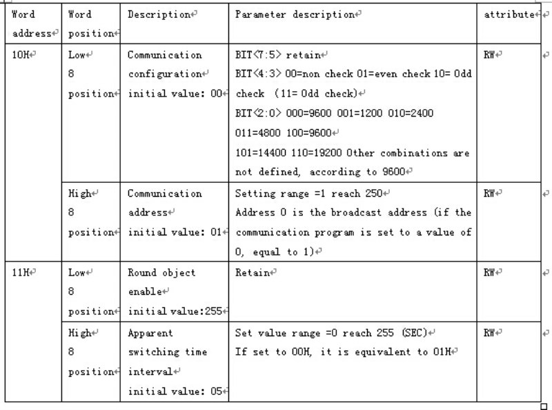
6.1 function code 03H (read), 06H (write)
Parameter set register information table
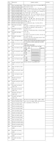
6.2 function code 03H (read)
Data register information table
Device output code to the input signal voltage conversion chip reference voltage VREF=0.256V
?

