Type:Logic ICs
Condition:New
Basic functions:Support standard MODBUS devices such as text, touch screen, PLC, etc.- 16-way DC transistor output, single-way maximum 500 mA
- Two high-speed pulse output, maximum 20K frequency.
- 1-way standardFour85 communication port (supporting modbus-RTU protocol)
Code Function Support Function Code:
| Function code | Definition | Operations (binary) |
| 0x02 | Read switch input | Read one or more switch state input data |
| 0x01 | Read switch output | Read one or more switch output status data |
| 0x030x04 | Read register data | Read data from one or more registers |
| 0x050X0F | Write switch outputWrite multiple switches | Control all the wayRelay"Hop / sub" output |
| 0x06 | Write single path register | Write a set of binary data into a single register |
| 0x10 | Write multiplexer register | Write multiple sets of binary data into multiple registers |
**************************************************************************************************************
MODBUS address1
Baud rate: 96008Bit data bits1 bit stop bitsNo check
0X0001~0X000F 16-way DC transistor output(The second set of Q7, Q8 is high-speed PWM pulse output) 4
X0065 First Pulse Frequency Value(max 20K) 4
X0066 Second Pulse Frequency Value (max 20K)4
X0067 first pulse duty cycle (value: 0-100) 4
X0068 number oneTwoRoad pulse frequency(Values: 0-100)
**********************************************-Read analog input (0x04)
Host sends:Addr 04 regH regL NumH numL crcH crcL
From the machine back:Addr 04 len d0H d0L...DnH dnL crcH crcL
Interpretation: Register address from0Start counting.numH numLRepresents the number of routes of the analog quantity to be read. This card has 5 analog input channels.10bitADCEach analog takes up two bytes of data. For example, to read the2Lu He3The register address is0001The number of registers is0002 For example, to read all analog quantities1Lu Zhi di8The address of the register is uuuuuuuuuuuuu0000The number of registers is0008 Return data0-0x3FFRepresents the collected analog quantities, such as analog quantities.0-20mAThe data read are18CThe decimal number is396So the current value isI = 20mA*396/1023 = 7.742mA Sensors are generally4-20mAIf the reading value is less than4mAThe connection line is faulty.
Example: read the first1Lu Zhi di8Road analogue
Host sends:01 04 00 00 08 F1 CC
From the machine back:0104 0C d0H d0L...D5H d5L crcH crcL
-Analog quantityInput and outputVC source code(clear notes):// Read the status of a single register
//ip_Addr slave MODBUS address
//data_Addr Data Storage Register Address
UInt16 readBUF (byte ip_Addr, UInt16 data_Addr)
{
UInt16 crc; //check value
Byte [] MSG = new byte [8]; // instruction arrayMSG [0] = ip_Addr; //slave address
MSG [1] = 0x04; // Read a single register
MSG [2] = byte (data_Addr > 8); high bit of // register address
MSG [3]= (byte) data_Addr; low bit // register address
MSG [4] = 0x00; high bit of data length to read
MSG [5] = 0x01; the base length of the data to be read
CRC = CRC16 (msg, 6);
MSG [6] = byte (crc > 8); 8 digits higher in // check
MSG [7] = (byte) crc; //check low 8 bits
Comm.Write(msg); //Send Read Request Zheng
Receive_A_Frame(); //Receive the Zhen reply signal
// Add here: Judge the received data
}
...More source code, please contact the seller after buying.-
-
-
Wiring diagram of two-wire sensor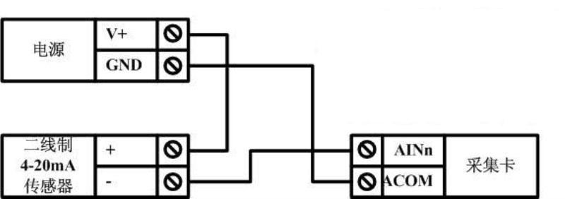
-Wiring diagram of three-wire sensor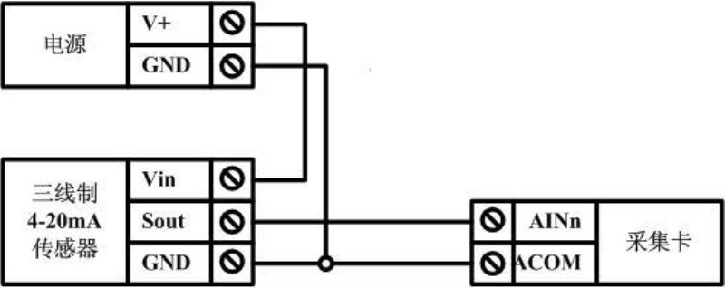
-Wiring diagram of four-wire sensor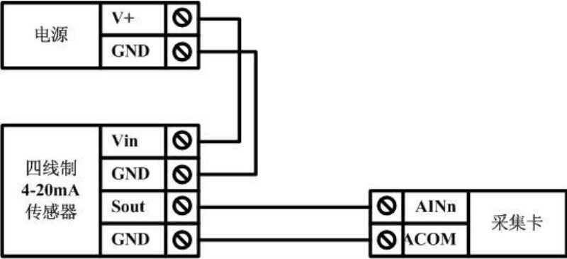
-Provide free testing softwareTen sets of coils are mandatory on the right and 10 coils are read on the left.Ten sets of forced coils are on the right and 10 coils are read on the left (2)Forced single coilOn the right, 10 sets of registers are mandatory, and on the left, 10 are read.
registervalue
Table of specific parameters
Output current parameters | AC1Class load | Maximum7A |
| AC3Class load | Maximum2A |
| AC5Class load | Maximum1A |
| DCload | Maximum10A |
| | |
Digital Input Characteristics | Maximum voltage | 36VDC |
| Minimum voltage | 9VDC |
| Recommended voltage | 9-30VDC |
| Input current | 4~20mA |
| | |
Analog input characteristics | Voltage range | 0~10V |
| Input current | 4~20mA |
| Resolving power | 10Bit<0~1023> |
| Conversion speed | 250K <4us/cycle> |
| | |
Serial port characteristic | level | standard232level |
| baud rate | 9600bps <Configurable> |
| Communication protocol | Modbus_RTU |
| | |
Input power characteristics | Voltage |
Q1: What Is Your Product Warranty?
A: We Guarantee Our Product Is Fit For Its Normal User Purposes And Is Free From Defects In Materials Or Workmanship.
Q2: What Is Your Company Policy On Defective Goods?
A: Our Company Keep Items Quality For A Long Time. If There Are Any Defective Goods Due To
Production Defects Or Transportation Problem, Please Contact Us. Our Customer Service Team Will Provide Immediate Response To
Complaints. We Will Try Our Best To Give You A Good Resolve Way.
Q3: What Is Your MOQ (minimum Order Quantity)?
A: Generally Our Moq Is No Limited. Please Have More Discussion With Us If Your Combination Of Models Is Complicated.
Q4:how About Getting Samples From You?
A: We Will Send You The Samples After We Receive The Payment For Samples. The Buyer Shall Afford The Shipping Cost. Please Have A
Confirm With Us Which Shipping Way Do You Want.
Q5:about The Shipment: What Type Of Shipment Will You Use?
A: We Usually Ship The Products By Express(delivery It To Your Door) Or By Air Freight To Your Nearest Airport, Shipping Days:3-7
Working Days Depend On Destination;if The Order Quantity Is Large, We May Ship By Sea Container And The Best Ship Way Is By Sea,
Shipping Days: Over 20 Working Days Depend On Destination Port.
Q6:what Packing Do You Use?
A: Neutral Package With Airbag Or Customized Package.
Q7:how Much Are The Shipping Cost?
A:shipping Cost Is Charged By The Package's Weight And Related To The Shipping Methods You Choose And Your Destination.
Q8:how To Order?
Step1.Click (Add to Cart) Buy Directly On The Product Page, Or Add To Shopping Cart And Settle Together, Pay With Paypal,
Need your information, such as full name,country, city, detail address, post code, tax number ...
Step2. We Will Delivery by EMS POST, FedEx or DHL Within
3-5 Working Days After Payment Confirmed.
Setp3. Confirm Us Receipt of Products.

