Type:Logic ICs
Condition:New
Model:BH4TDV
The latest edition of U5 LINK, patch technology.
Original imported advanced FT-232RL USB interface chip, plug-and-play, heavy industry and heavy materials supporting finished cables, interface concise and standard, complete full mode LINK.
(Note: Upgrade to black case, black panel, the following instructions quote picture may not be black, object-oriented, avoid misunderstanding)
Standard configuration: a total of 1 interface boxes, 5 lines.
U5-8X7 hosts 1.
The USB line is 1 (genuine HP HP original magnetic ring).
original audio line 2 (true screen).
Customized DATA data line 1(real shielding),
CAT remote control line 1(real shielding).
Wecombines rich manufacturing experience, responds to the international mainstream plug-and-play concept, strengthens design, optimizes interface, and introduces a new version of MINI link U5 radio communicator, plug-and-play, compact and portable, compatible with a variety of working modes, suitable for a variety of application environments.
Full software support:
HRDDM780LOGG32NIMMWriteLogECHOLINKpasyPalSSTVCw_playerAPRSAGWTrackerMMTTYMMVARIMIXW et al.
Performance brief:
* imported high quality FT-232RL USB interface chip.
* SMT process
* imported 6N137 high speed communication optocoupler, with communication speed up to 115200.
* supporting mechanism for finished data cable connection, plug and play.
* radio remote control interface support: all optical isolation, CAT remote control support 115200 stable high-speed communication.
* complete signal support: contains TXDRXDRTSDTRCTS signals.
* support for SQL control and CTS signal introduction.
*Specially customized high quality audio isolation transformer with shielding isolation and no AC noise.
Plug and play, no need to set up, no external power supply.
* standardized voice / data radio interface: DATA (MINI DIN 6 specification)
* standardised CAT remote control interface: CAT (MINI DIN 8 specification)
* professional wave soldering process with high technology level.
* digital mode optimization of ground wiring structure.
Support radio model:
YAE SU: FT-891 FT-991FT-817857897780088008900100D, etc.
I COM support: IC-2710, 2720, 2820 and 703 (only data interface, PACKET), 706 (Only data interface.PACKET), 7000 (Only data interface.PACKET)
KEN WOOD support: TM-V71, TS-480 (DATA only), etc.
Hand station: support
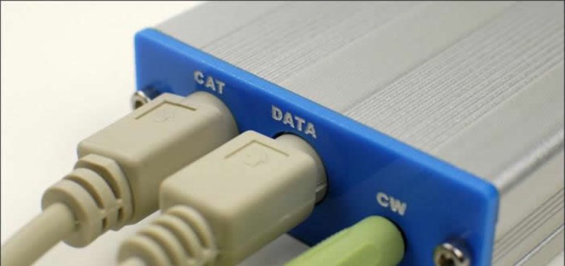
Wiring diagram:
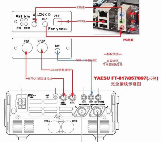
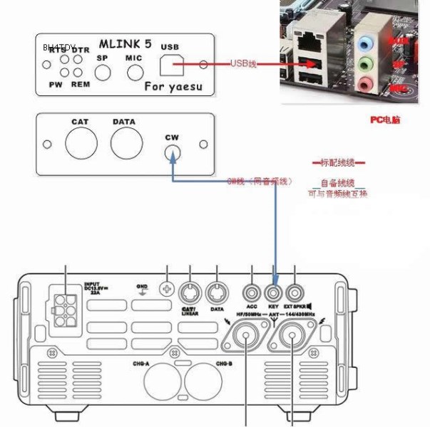
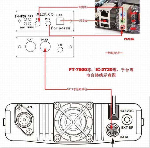
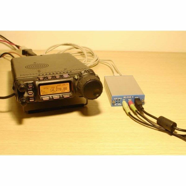
Application wiring example:
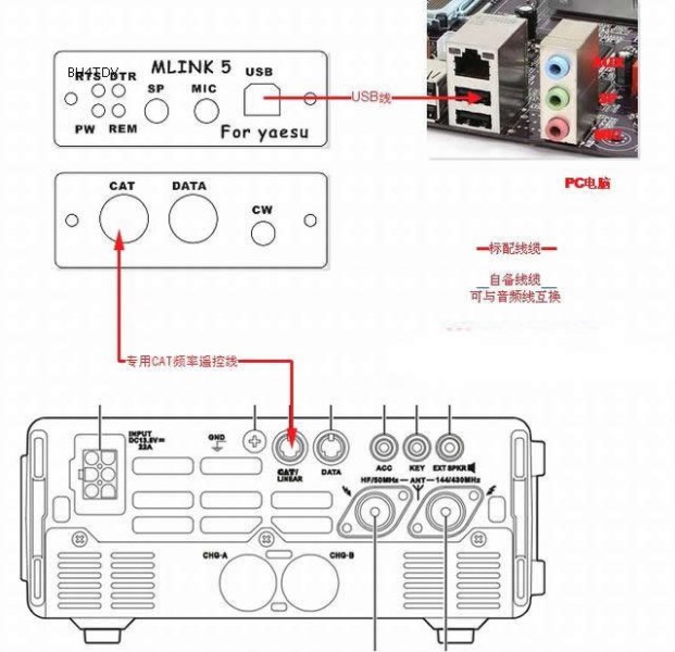
FT-817 857897 uses only CAT instances.
FT-817 857 897 uses only CW instances.

FT-817 857 897 uses only DATA instances.
FT-780088008900100D and other UV stations.I COM:IC-2710, 2720, 2820 and 703 (only UV), 706 (only UV), 7000 (only UV), etc.Same connection.
An example of building arms compatible hand stand connection.
Frequently asked questions FAQ:
1, how to set up DTRRTS of U5?
Answer: Connector itself does not need any settings, all kinds of application settings RTS = PTT, DTR = CW, CTS = SQL (when needed).
2, how to send CW?
Answer: U5 CW port output equivalent to a hand key contact on-off signal output, by computer software DTR signal control, using CW line (pull-out audio line, equivalent to audio line) to connect CW and radio keys, radio set hand key mode, all kinds of transmission software set CW = DTR.
3, using 817, 857, 897 radio, HRD can not connect, display frequency?
Answer: the USB port number in HRD is selected. It is not clear whether the port number is selected automatically or to the device manager. Communication rate selection should be consistent with the radio's own rate settings, FT-897 radio 19 menu view or adjustment. Radio No. 20 menu should be set to CAT.
If the USB port number is larger than 10 after the driver is installed, the USB port number <10, such as COM2, should be set up in the device manager.
Matching CAT cable is square, some of the station's CAT socket is deep, may not be inserted at the bottom, so that poor contact, cut off a bit of CAT cable square edge of the plastic, so that the cable can be inserted to the end.
The above check is correct, still can not link the computer, check whether the radio CAT socket 13.8V power output (radio CAT interface pin definition refers to FT-857D English manual 32 pages), no output, check and replace the radio built-in small insurance resistance.
3A, I use HRD software, FT-897D radio, can correctly display the frequency, but connect to HRD radio that PTT launch?
Answer: RTS, DTR do not hook, RTS hook, after connecting PTT trigger long hair.
3B, I use HRD, each time, sometimes find the normal connection port number display frequency, sometimes can not find the port number, reopen the HRD and port number, what is the problem?
Answer: With HRD software, you need to connect USB first, then open the HRD software, otherwise HRD can not retrieve the USB port number.
4, CW setup in HRD software?
There are 2 kinds of settings:
1, keyed CW: selects CW, and "MODES+IDS" sets KEY port and keyed output DTR to hook. If you need PTT, check "USE PTT".
2, audio CW: select MCW, select PTT=RTS, or turn on the radio voice control.
4a, I use HRD software, FT-897D radio, has been able to correctly display the frequency, DM780 software, PSK31, SSTV, etc. can be received, but can not be launched, how to set?
Answer: DM780 software has two ways to control PTT transmission, one is command mode (radio support), the other is RTS signal control mode. Software default is command mode.
1) Command mode control station PTT, if the station has been displayed in the HRD starting interface frequency, and radio support command control PTT.
Press F8 in DM780, PTT is selected in the left list, HRD is selected in the middle item on the right, and it is set. TX icon will be displayed after setting.
2) HRD uses command to control PTT by default. If the radio does not support command mode, RTS signal can be selected to control PTT transmission.
In HRD frequency operation main interface, press F8, left side list to select COM PROT TX, right COM PROT PIN select RTS.
5. I use U5 LINK YAESU small box, connected to FT-817, PKT mode, may control the launch, but the platform monitor no sound, feel DATA line is loose?
Answer: The matching DATA cable is a square port. The DATA socket of some radio stations is deep, and may not be inserted at the bottom, so that the contact is not good.
6, how do I test whether the audio transceiver circuit of U5 LINK is normal?
Answer: Pull out all the links of LINK, LINK SP and computer SP are connected with audio cable, the volume of the computer is turned on, the computer plays a MP3, LINK MIC connects the headset, find a small capacitor or thin wire, short LINK DATA socket 1, 5 feet, the headset has music to indicate that the audio signal circuit is normal.
7, use the DATA interface FT-897D, in the UV segment can control the launch, no signal output?
Answer: Refer to page 37 of FT-897D English Manual, press MODE mode key to switch to PKT mode, when the PKT marker is lit, the radio internal electronic switch to DATA interface.
8. How does U5 for YAESU connector connect to the hand stand? Which platforms do you support?
Compatible interface of many
If the U5 for ICOM connector is used to connect the handset, it is necessary to connect the power supply of about 5V from ACC separately for triggering PTT.
9. U5 LINK connects the desktop computer and the radio. The desktop computer used to send and receive SSTV normally. Now it connects the notebook computer, sends normally, receives the image tilted or can not receive. What's the problem?
Answer: It has nothing to do with LINK, you will find that without LINK, two computers and sound card direct audio line will be the two sound card cross docking, MIC-SP, SP-MIC, also can not decode.
This phenomenon is related to the sound card clock, different sound card clocks will be slightly different, clock differences will cause sampling frequency offset, resulting in difficult decoding or unable to decode.
If you encounter this problem, use 2 computers to connect the dual sound card with the audio line, MIC-SP, SP-MIC. Both computers turn on SSTV software, transmit test frequency selected 1900, transmit test audio, receive computer to observe whether the peak of audio sampling is 1900, if different, the option - - set MMSSTV - - other - - clock, select different clocks, so that the sampling frequency is correct.
Similarly, some software using sound card decoding, such as APRS, sound card clock is different, will also cause the situation that can not be decoded, need to check whether there are clock adjustment options in the application software, such as no options, can only choose hardware TNC decoding.
10, using DATA interface to connect FT-450, when launching, the station automatically jumps to CW mode? How to connect the remote control frequency?
Answer: Refer to page 73 of the FT-450 English Manual, press the MODE mode key on the radio, switch to the DATA interface, and the DATA marker is lit.
The FT-450 remote control frequency still uses the original RS-232C interface of the radio, and connects the serial port with the serial port line alone. Or use the FT-450 special edition, occupying only 1 USB ports of the computer.
11, FT-950 radio, unable to trigger PTT launch?
Answer: For FT-950, please specify 950 before ordering, and add a relay to trigger PTT when shipping. This service has stopped, and FT-950 dedicated LINK will be launched.
12. Can you integrate USB sound card so that two audio wires can be omitted when connecting to the computer?
Answer: For the time being, from the test experiments of several commonly used USB sound cards on the market, using USB sound cards will make the application settings more troublesome. Some software can not decode by using USB sound cards. The main phenomena encountered in the test after interference are: sudden silence, sudden distortion, opposite sound channels, and damage at the same time. The probability is relatively large, and some of the faults are more subtle, which makes it difficult to exclude. If you encounter USB sound card failure, you can quickly find and solve problems, otherwise it is not recommended to use.
13, which is stable for USB interface and RS-232C serial port?
Answer: The old question, in the industrial field has long been a conclusion, the current market USB RS232C serial port devices are not native RS232C serial port stability (electromagnetic interference environment), but the contradiction is that almost everyone is using a notebook control station, the current notebook computer basically do not provide the original RS232C serial interface.
14, I control the phenomenon of radio control out of control, how to deal with it?
Answer: often occurs and uses the sky tune environment.
USB port usage note:
USB is a digital-analog mixed signal of high-speed communication, so it is very sensitive compared with the common 232 serial port. Radio transmitter and leakage of RF wave will affect the normal operation of PC and PC peripherals (such as USB).
A simple verification method can explain the problem, the power of the desk can be lowered to L, close to the USB mouse launch, computer cursor position immediately fly away or fail to move, need to re-plug the USB mouse to reset the USB device.
Therefore, strong RF interference will also cause the USB port of the transmitter to be out of control and unresponsive.
The commonly used USB-232 (TTL) conversion chips are FT-232RL, CP2102, PL2303 and so on. Any chip will be invalidated by electromagnetic interference.
In a relatively strong electromagnetic interference environment, it is recommended to use RS-232 serial port connector.
Port out of control approach: reconnect USB port and restart application software.
Ways to improve: (1-5 points)
1, radio and power good grounding, poor grounding, easy to cause radio equipment radio frequency interference increase.
2, radio, radio power, computers, should be connected to the same ground wire, to maintain good grounding contact.
3. Adjusting antenna resonance, reducing standing wave, avoiding high standing wave transmission, reducing interference to USB and computer equipment, and prolonging the life of the radio. Large standing wave transmission will cause unnecessary damage to the radio power amplifier parts.
Try to avoid the use of the sky tune, so that the antenna resonant, can not avoid the use of the sky tune, pay attention to the installation position of the sky tune (refer to the sky tune manual), as far as possible to reduce standing wave.
4, USB line, audio frequency line, data line, remote control line and other cable clip magnetic ring.
5. When the distance between the communicator and the radio is pulled apart, the distance between the antenna and the communicator must be kept at least one meter or more (when the transmitting power is 2W), the greater the transmitting power, the greater the distance, until it has no effect.
6. Use external antenna (for example, magnetic sucker antenna pedestal with extension line).
7. Check the connection of the radio feeder, welding and connecting firmly to reduce leakage.
8. Use linear power to power the radio.
9, notebook can try to use only laptop battery work.

