Condition:New
Type:Logic ICs
■Basic features
●The power supply voltage is DC24V (DC18-26V is applicable)
●The amplifier can be connected to 1 or 2 tension load cells with output 150-300mV
●With the auxiliary power supply DC5V output required by the tension sensor
●The amplifier amplifies the sensor signal and outputs the standard 0-10V
●With zero and full scale adjustment, there are corresponding indicator lights, easy to operate
●The output linearity is 0.1%, high precision, good stability, and strong anti-interference ability
●Transmitter output can be directly connected with PLC, display control instrument
●DIN rail type installation, easy to install
●Outer dimensions: height 117×width 100×thickness 36mm
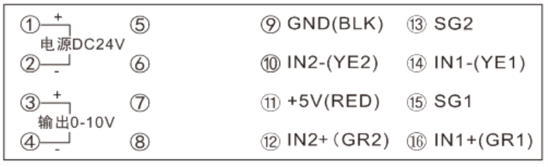
■Input wiring
●Transmitter wiring diagram
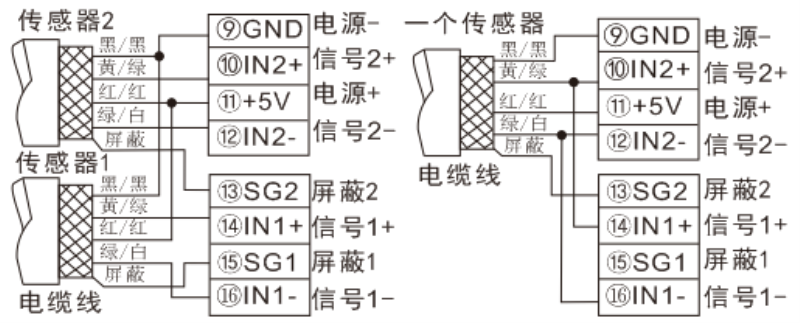
●Connection of tension sensor to amplifier:
The sensor wiring should be in accordance with the sensor manual, there are usually two lead colors:
1. Power+(red wire)/power-(black wire)/signal+(yellow wire)/signal-(green wire)
2. Power + (red wire) / power-(black wire) / signal + (green wire) / signal-(white wire)
*The sensor lead usually has a shielding net, which can be connected to SG1 or SG2, if not, you can leave it alone
Q1: What Is Your Product Warranty?
A: We Guarantee Our Product Is Fit For Its Normal User Purposes And Is Free From Defects In Materials Or Workmanship.
Q2: What Is Your Company Policy On Defective Goods?
A: Our Company Keep Items Quality For A Long Time. If There Are Any Defective Goods Due To
Production Defects Or Transportation Problem, Please Contact Us. Our Customer Service Team Will Provide Immediate Response To
Complaints. We Will Try Our Best To Give You A Good Resolve Way.
Q3: What Is Your MOQ (minimum Order Quantity)?
A: Generally Our Moq Is No Limited. Please Have More Discussion With Us If Your Combination Of Models Is Complicated.
Q4:how About Getting Samples From You?
A: We Will Send You The Samples After We Receive The Payment For Samples. The Buyer Shall Afford The Shipping Cost. Please Have A
Confirm With Us Which Shipping Way Do You Want.
Q5:about The Shipment: What Type Of Shipment Will You Use?
A: We Usually Ship The Products By Express(delivery It To Your Door) Or By Air Freight To Your Nearest Airport, Shipping Days:3-7
Working Days Depend On Destination;if The Order Quantity Is Large, We May Ship By Sea Container And The Best Ship Way Is By Sea,
Shipping Days: Over 20 Working Days Depend On Destination Port.
Q6:what Packing Do You Use?
A: Neutral Package With Airbag Or Customized Package.
Q7:how Much Are The Shipping Cost?
A:shipping Cost Is Charged By The Package's Weight And Related To The Shipping Methods You Choose And Your Destination.
Q8:how To Order?
Step1.Click (Add to Cart) Buy Directly On The Product Page, Or Add To Shopping Cart And Settle Together, Pay With Paypal,
Need your information, such as full name,country, city, detail address, post code, tax number ...
Step2. We Will Delivery by EMS POST, FedEx or DHL Within
3-5 Working Days After Payment Confirmed.
Setp3. Confirm Us Receipt of Products.

