Brand Name:icchipcn.com
Condition:New
Type:buck (stepdown) regulator
Model Number:MBSL2AI2RO
Chapter 1 Product Introduction
1. Product overview
? ? MBSL2AI2RO?module is 2-way 0/4?~?20mA?analog input,?2?-way switch output (relay output), output through RS485 interface.?The module adopts standard Modbus RTU communication, which can be directly adapted to various upper computer configuration software, PLC, DCS, etc.
? ?1. RS485 MODBUS RTU standard communication is adopted?,?which can be networked with upper computer configuration software, PLC, industrial touch screen, etc.,?with communication status indicator
? ?2.?The communication circuit adopts lightning protection, anti-interference design and?power polarity protection.
3.?The RS485 communication signal output interface adopts overvoltage and overcurrent double protection.
4.?It can be widely used in signal acquisition and control of industrial field equipment.
5.?The communication format can be set by software.
2. Main technical indicators
project | technical indicators |
Analog input signal | 1.?Analog input?channel:?2?-channel acquisition 2.?Analog input type:?0-20mA/4-20mA?analog signal 3.?Analog input accuracy?: ±0.1 4.?Resolution: 12bit 5.?External power supply: DC9V~30V |
digital signal output | 1.?Output channel: 2 digital outputs 2.?Load capacity: resistive load 5A/channel |
communication | 1?.?Communication protocol: MODBUS-RTU 2?.?Interface type: isolated RS485 communication, the output interface adopts overvoltage and overcurrent double protection 3?.?Baud rate: 4800bps, 9600bps, 19200bps, 38400bps, 57600bps, 115200bps 4?.?Parity bit: no parity, even parity, odd parity 5?.?Setting method: module address, baud rate, check digit can be set by software 6?.?Communication distance: @9600bps 1200 meters |
Module size and installation method | 1. Installation method: standard DIN rail installation or screw installation 2.?Dimensions:?100?×55×32mm |
working environment | Temperature:?-10?~+70?℃ Humidity: 35?~85%?(no condensation) |
Working power | 1?.?Power supply voltage: 10V ~ 30V wide range power supply, with power polarity protection 2?.?Power consumption: less than 2W |
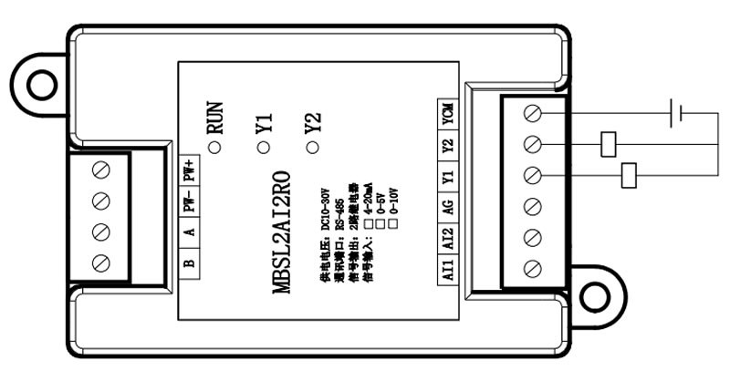
3. Interface definition
Terminal name | illustrate | Terminal name | illustrate |
PW+ | External power input positive terminal | A | RS485?signal A+ |
PW- | External power input negative terminal | B | RS485?signal B- |
Y1 | Digital output channel?1 | AI1 | Analog input channel?1 |
Y2 | Digital output channel?2 | AI2 | Analog input channel?2 |
YCM | Digital output common port | AG | Analog input ground |
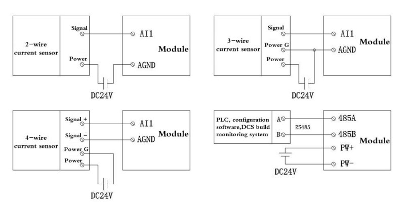
4.?Module wiring diagram
Chapter 2?Description of Modbus?Registers and Communication Protocol
one.?MODBUS function codes and address ranges supported by the module
1?.?MODBUS function codes supported by the module
two.?Register definition description
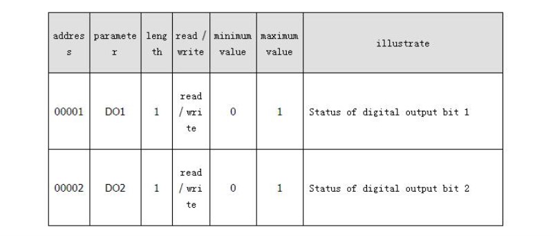
1.?Output coil register (function code:?0x01H?,?0x05H?,?0x0FH?)
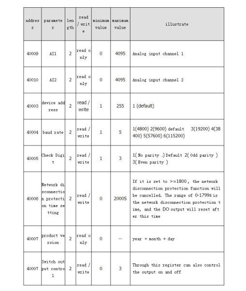
2.?Holding registers (function code:?0x03H?,?0x06H?,?0x10H?)
3.?Calculation method for converting channel sampling values into actual data
1.?,?0-20mA?input: actual value?=?collection value?(?decimal form?) *?20 mA?/ 4096
2.?? 4-20mA?input: actual value?=?(?(acquisition value?(?decimal form?)-819?)?*?(?20-4?)?/ (4096-819)?)?+4
For example: if channel?0?is set to?4-20mA?input, the data read by communication is?0x07D0H?, the converted decimal is?2000?, and the calculation formula is:?((1181*16) / 3277) +4= 9.76mA
?Note: "Acquisition value" is the original digital value, and "Actual value" is the converted actual current value.?practical application
?The?20 mA here?can also be changed to the upper limit of the engineering quantity.

