Condition:New
Type:Logic ICs
Chapter One Product Introduction
1. Product overview
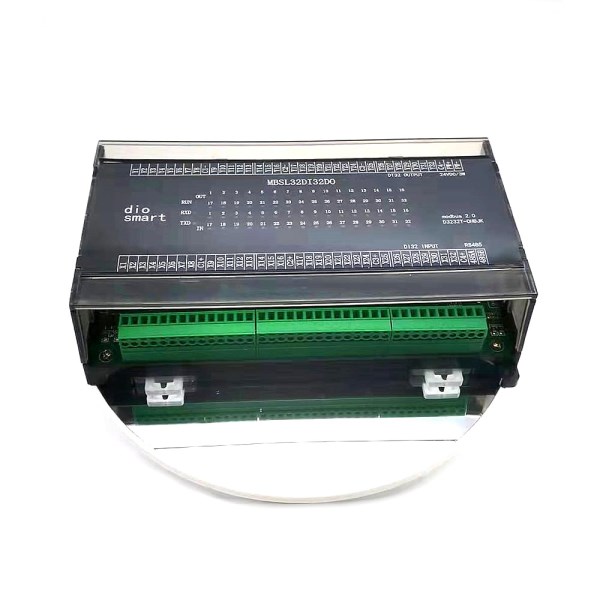
MBSL32DI32DOThe module is a 32-channel digital isolated input and 32-channel digital transistor isolated output module, which is output through an isolated RS485 interface. The module adopts standard Modbus RTU communication, which can be directly adaptedVariousHost computer configuration software, PLC, DCS, etc. The module power supply and RS485 communication electrical signals are isolated from each other, effectively suppressing various serial mode and common mode interference, while also ensuring the stable and reliable operation of the module.
1,Using RS485 MODBUS RTU standard communication, it can be networked with host computer configuration software, PLC, industrial touch screen, etc.With communication status indicator
2, Signal control, power supply, and RS485 communication electrical signals are isolated from each other.
3, The communication circuit adopts lightning protection and anti-interference design,Power polarity protection.
4, RS485 communication signal output interface adopts double protection of overvoltage and overcurrent.
5, Can be widely used in the signal acquisition and control of industrial field equipment.
6, The communication format can be set by software.
2. Main technical indicators
project
|
Technical index
|
Signal input/output
|
1, Input channel: 32 digital inputs
2, Output channel: 32-channel transistor
output
3, Load capacity: resistive load
1A/channel
|
Communication output
|
1. Communication protocol: MODBUS-RTU
2. Interface type: isolated RS485
communication, output interface adopts double protection of overvoltage and
overcurrent
3. Baud rate: 4800bps, 9600bps,
19200bps, 38400bps, 57600bps, 115200bps
4. Parity: no parity, even parity, odd
parity
5. Setting method: module address, baud
rate, parity bit can be set by software
6. Communication distance: @9600bps
1200m
|
Module size and installation method
|
1.Installation
method: standard DIN rail installation or screw installation
2,Dimensions:
180×98×52mm
|
working environment
|
Temperature: -40~+85?Humidity: 35~85%(No
condensation)
|
Power supply
|
1. Power supply voltage: 10V28V wide
range power supply, with power polarity protection
2. Power consumption: less than 5W
|
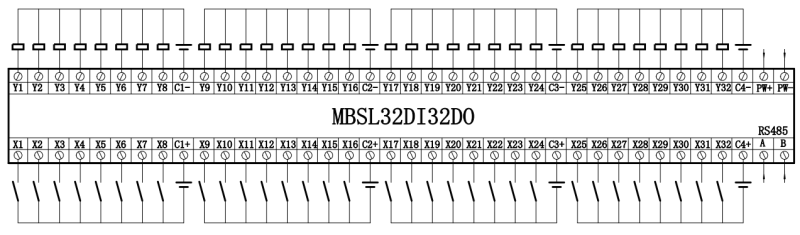
Three, interface definition
Terminal
name
|
Saybright
|
Terminal
name
|
Saybright
|
PW+
|
External
power input positive terminal
|
485A
|
RS485Signal
A+
|
PW-
|
External
power input negative terminal
|
485B
|
RS485Signal
B-
|
X1
|
Digital
input channel1
|
YO1
|
Digital
output channel1
|
X2
|
Digital
input channel2
|
YO2
|
Digital
output channel2
|
X3
|
Digital
input channel3
|
YO3
|
Digital
output channel3
|
X4
|
Digital
input channel4
|
YO4
|
Digital
output channel4
|
X5
|
Digital
input channel5
|
YO5
|
Digital
output channel5
|
X6
|
Digital
input channel6
|
YO6
|
Digital
output channel6
|
X7
|
Digital
input channel7
|
YO7
|
Digital
output channel7
|
X8
|
Digital
input channel8
|
YO8
|
Digital
output channel8
|
C1+
|
entercom1
|
C1+
|
Outputcom1
|
X9
|
Digital
input channel9
|
YO9
|
Digital
output channel9
|
X10
|
Digital
input channel10
|
Y10
|
Digital
output channel10
|
X11
|
Digital
input channel11
|
Y11
|
Digital
output channel11
|
X12
|
Digital
input channel12
|
Y12
|
Digital
output channel12
|
X13
|
Digital
input channel13
|
Y13
|
Digital
output channel13
|
X14
|
Digital
input channel14
|
Y14
|
Digital
output channel14
|
X15
|
Digital
input channel15
|
Y15
|
Digital
output channel15
|
X16
|
Digital
input channel16
|
Y16
|
Digital
output channel16
|
C2+
|
enterCOM2
|
C2-
|
OutputCOM2
|
X17
|
Digital
input channel17
|
Y17
|
Digital
output channel17
|
X18
|
Digital
input channel18
|
Y18
|
Digital
output channel18
|
X19
|
Digital
input channel19
|
Y19
|
Digital
output channel19
|
X20
|
Digital
input channel20
|
Y20
|
Digital
output channel20
|
Xtwenty
one
|
Digital
input channel21
|
Y21
|
Digital
output channel21
|
Xtwenty
two
|
Digital
input channel 22
|
Y22
|
Digital
output channel22
|
X23
|
Digital
input channel23
|
Y23
|
Digital
output channel23
|
Xtwenty
four
|
Digital
input channel24
|
Y24
|
Digital
output channel24
|
C3+
|
entercom3
|
C3-
|
Outputcom3
|
X25
|
Digital
input channel25
|
Y25
|
Digital
output channel25
|
X26
|
Digital
input channel26
|
Y26
|
Digital
output channel26
|
X27
|
Digital
input channel27
|
Y27
|
Digital
output channel27
|
X28
|
Digital
input channel28
|
Y28
|
Digital
output channel28
|
X29
|
Digital
input channel29
|
Y29
|
Digital
output channel29
|
X30
|
Digital
input channel30
|
Y30
|
Digital
output channel30
|
X31
|
Digital
input channel31
|
Y31
|
Digital
output channel31
|
X32
|
Digital
input channel32
|
Y32
|
Digital
output channel32
|
C4+
|
entercom4
|
C4+
|
Outputcom4
|
5. Communication description
1, Communication parameter description (factory
value): 9600, N, 8,
parameter
|
illustrate
|
9600
|
Baud rate
|
N(No
verification)
|
Check
Digit
|
8
|
Data bit
|
1
|
Stop bit
|
Q1: What Is Your Product Warranty?
A: We Guarantee Our Product Is Fit For Its Normal User Purposes And Is Free From Defects In Materials Or Workmanship.
Q2: What Is Your Company Policy On Defective Goods?
A: Our Company Keep Items Quality For A Long Time. If There Are Any Defective Goods Due To
Production Defects Or Transportation Problem, Please Contact Us. Our Customer Service Team Will Provide Immediate Response To
Complaints. We Will Try Our Best To Give You A Good Resolve Way.
Q3: What Is Your MOQ (minimum Order Quantity)?
A: Generally Our Moq Is No Limited. Please Have More Discussion With Us If Your Combination Of Models Is Complicated.
Q4:how About Getting Samples From You?
A: We Will Send You The Samples After We Receive The Payment For Samples. The Buyer Shall Afford The Shipping Cost. Please Have A
Confirm With Us Which Shipping Way Do You Want.
Q5:about The Shipment: What Type Of Shipment Will You Use?
A: We Usually Ship The Products By Express(delivery It To Your Door) Or By Air Freight To Your Nearest Airport, Shipping Days:3-7
Working Days Depend On Destination;if The Order Quantity Is Large, We May Ship By Sea Container And The Best Ship Way Is By Sea,
Shipping Days: Over 20 Working Days Depend On Destination Port.
Q6:what Packing Do You Use?
A: Neutral Package With Airbag Or Customized Package.
Q7:how Much Are The Shipping Cost?
A:shipping Cost Is Charged By The Package's Weight And Related To The Shipping Methods You Choose And Your Destination.
Q8:how To Order?
Step1.Click (Add to Cart) Buy Directly On The Product Page, Or Add To Shopping Cart And Settle Together, Pay With Paypal,
Need your information, such as full name,country, city, detail address, post code, tax number ...
Step2. We Will Delivery by EMS POST, FedEx or DHL Within
3-5 Working Days After Payment Confirmed.
Setp3. Confirm Us Receipt of Products.

