Condition:New
Type:Logic ICs
5.5 " black and white TV kit / partsElectronic parts production
The 5.5-inch black-and-white TV Set Kit is designed by engineers through careful material selection, debugging and design after repeated experiments. Full shielded magnet steel transformer is used in this TV set, which completely overcomes the interference of transformer's strong magnetic field to the picture tube, and makes the overall performance optimized. The components are tested and screened strictly. This machine has advanced principle, reasonable layout of components and beautiful appearance. It corrects the shortcomings of the same type of machine, such as character confusion and errors, and improves the success rate of assembly.
Product Dimensions: 185*178*150mm:
1. The main parameters of this machine:??The input of the power transformer is AC 220V, the output is AC 12V, the external DC input voltage is 12V, the current of the whole machine is 0.8A-1.2A, the filament voltage of the kinescope is 6.3V (effective value), and the anode high voltage is 6-7V. The antenna input impedance is 75Ω, the video input impedance is 75Ω, the image clarity is greater than 380 lines, and the audio output power is 10W.?
2. Circuit principle(for more clear send by email):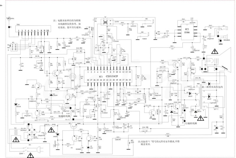 3, black and white TV signal flow
?The TV signal is received by the antenna and sent to pin 1 of the electric tuning tuner TDP. The high frequency signal (above 48MHZ) is high-amplified and mixed here, and becomes the first audio intermediate frequency signal of 38MHZ image intermediate frequency and 31.5MHZ each . Then the output from pin 9 is sent to Q201 for pre-mid-amplification. The signal output of Q201 is sent to the surface acoustic wave filter, which has the special frequency characteristics required by the TV. It only allows the 38MHZ image intermediate frequency and the 31.5MHZ first audio intermediate frequency signal to pass according to certain requirements. Other signals are filtered out or absorbed. After the surface acoustic wave filter, the signal enters the ICI integrated circuit 1 and 28 feet, after internal signal processing, the ICI integrated circuit 5 outputs the composite full TV signal (including 0-6MHZ video signal, 6.5MHZ second audio signal, line Field synchronization signal, etc.), sent to the final viewing tube Q801 for image signal amplification, and then input to the cathode of the kinescope after amplification. The instantaneous value of this signal represents the size of a certain pixel on the screen (changes the strength of the cathode emitted electrons) and the other part is sent to the ICI integrated circuit 6 pin for synchronization separation. After the synchronization signal is separated, the frequency of the line and field oscillators is measured. control. Keep the frequency and phase of the line and field oscillations strictly consistent with the signal transmitted by the TV station (to achieve the same frequency and phase). Only by doing this can a complete image be formed on the screen. A part of the signal is sent to the audio channel through C17, Y1 (6.5MHZ ceramic filter) for audio demodulation, and the adjusted audio signal is sent to the IC2 integrated circuit for amplification, and the amplified signal drives the speaker to make the speaker emit sound.?
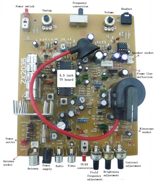
4, the working principle of each part of the ZX2035 black and white TV?
1. Power supply circuit?Transformer T01 steps down 220V AC power to 12V, which is pulsating DC power after D21-D24 bridge rectification and C21 filtering. Q701 is a regulator tube, Q702 is a drive tube, Q703 is a sampling amplifier tube, and ZD701 is a voltage regulator whose voltage is used as a quasi-voltage source. R703, R704 and VR701 form a sampling loop. Adjusting the resistance of VR701 can change the voltage of the regulated power supply. The output voltage is adjustable between 9-12V. The rated output voltage of this machine is 10V.?
2. High frequency tuner and auxiliary circuit?This machine adopts UVD6201-RB type full-channel electronic regulator. There are ten pins: 1 pin is the antenna input terminal, 2 pin is the AGC automatic gain control terminal, 3, 5, 6 pins are the band selection control terminal, band selection The voltage is 9.1V, pin 9 is the TV IF signal output terminal, pin 10 is grounded, and pin 7 is idle.?When receiving wireless TV signals, the high-frequency signal received by the antenna is sent to pin 1 of the tuner via the ANTIN socket and capacitor C201. When receiving the cable TV signal, connect the wired cable plug to the ANTIN socket, disconnect the movable contact piece from the antenna, and connect the wired signal to the 1 pin of the tuner via C201.?The 4 feet of the tuner is the voltage input terminal, and the tuning circuit is composed of VR202, R215, C224, ZD201 and other components. Line output transformer 7 pins output +120V voltage after D603 rectification and C616 filtering, and 33V voltage is obtained through Zener diode Z201 and resistor 215. The tuning circuit composed of VR202 divides the voltage of 33 to 4 pins of the tuner. The voltage of pin 4 varies between 0-30V.?The 10V voltage provided by the power supply is used as the working voltage of the tuner and the band selection voltage to the tuner 8 pins and the band switch respectively.?
3. Public transit?The intermediate frequency signal (image intermediate frequency signal and first audio intermediate frequency signal) output from the 9th pin of the high-frequency tuner is sent to the pre-amplifier through C202 for amplification, and after amplification, the output of the Q201 collector set is coupled to the "surface acoustic wave" via C204 "Filter", after forming the mid-amp characteristic curve through "Surface Acoustic Wave Filter", it is sent to ICI (CD515ICP) integrated circuit 1 and 28, after the three-stage image intermediate frequency amplifier inside the IC, it is directly added to the video detector . The detected video signal is amplified in the pre-video amplifier circuit, and output from pin 5 after the noise is removed by the noise suppression circuit, and then coupled to the video amplifier output circuit through R802 and C802.?Inside the IC, another signal from the noise suppression circuit is added to the intermediate frequency AGC and the high-efficiency delay AGC circuit for processing, and the high-efficiency delayed AGC voltage is output from pin 3 and sent to the AGC end of the tuner via R209. Among them, R209 is the isolation resistance, C211 is the filter capacitor, and C314 is the high-frequency bypass capacitor. The 2-pin external potentiometer VR201 is used to adjust the high-amplification AGC delay. R206 and R207 are voltage divider resistors, and C206 is a bypass capacitor. The 4-pin external RC circuit C212, R211 determines the time constant of the AGC filter circuit.?
4. Video amplifier circuit?Q801 is a video amplifier output tube. Because this stage requires a large output signal amplitude, the collector power supply voltage needs about 50V. Q801 is connected into a resistance-capacitance coupling common emitter circuit. C804 is the output coupling capacitor. C808 is a collector load resistor, and its resistance has a great influence on the amplifier's gain and the width of the passband. The larger the resistance, the higher the gain and the narrower the passband.?When the contrast is small, the blanking impulse pulse in the full TV signal is not enough to completely stop the electron beam of the kinescope, so a retrace line will appear on the screen. In order to prevent the occurrence of such problems, a blanking circuit is added to the output tube of the video amplifier. The blanking circuit uses line and field scan reverse pulses to eliminate the retrace line on the raster.?The line and field blanking pulses of this machine are applied to the emitter of the video amplifier tube. The line reverse stroke is the 3 pin of the line output transformer and is added to the Q8 emitter through R58. The field reverse pulse is added to the emitter of Q8 through R34 and D11. . When the line or field reverse-travel positive pulse arrives, the amplifier tube is stopped, and the collector circuit presents a high potential, which effectively eliminates the reverse-travel regression line. After the blanking circuit is added to the AV tube, even if there is no TV signal input, there will be no flyback lines on the grating. Therefore, the presence or absence of a retrace line on the grating can be used as a sign for judging whether the output tube is normal.?VR802 is a contrast adjustment potentiometer. C805 is a DC blocking capacitor that provides an AC signal path. R812 and R811, R810, VR802 form an AC parallel circuit to control the AC feedback of the amplifier, thereby controlling the gain of the amplifier. OC3 high frequency compensation capacitor. R51 is a current-limiting resistor. When the display internally ignites, it limits the amplitude of the short-circuit current and plays a certain protective role.?
5. Sound channel?The first audio intermediate frequency signal (31.5MHZ), the second audio intermediate frequency signal (6.5MHZ) is different from the image intermediate frequency signal (38MHZ) in the IC internal detection stage. It is output from 5 feet of CD5151CP integrated circuit. This signal passes C307/101p, 6. 5MHZ band pass filter Y1 to take out the second sound signal and send it to CD5151 integrated circuit 7 feet. Pin 8 is also a pin of the audio intermediate frequency amplifier circuit, but because its external circuit is connected to C311, C312 AC bypass capacitors, it becomes a single-ended input differential amplifier circuit. The resistors R308 and R307 between pins 7 and 8 are the bias resistors of the audio intermediate frequency amplifier in the internal circuit.?The component T1 connected between pins 9 and 10 is the linear reactance conversion circuit (frequency detection loop) required by the internal peak frequency monitor circuit. The 11-pin output of the audio signal obtained after the frequency detector is externally processed, through R302, R300, C300, C301, C502, volume potentiometer VR301, C302; and then to the integrated circuit IC2 (D386P) 3 pin for audio signal amplification.?IC2 is an audio power amplifier integrated circuit. When the power supply voltage is 10V and the speaker impedance is 8Ω, the output power can reach 0.7W. It is a single-row 8-pin package integrated circuit with 3 pins as the inter-frequency input terminal. Pin 5 is the output terminal of the audio power amplifier, and the amplified audio signal is coupled to the speaker through the capacitor C305 to emit TV audio sound. Pin 2 and pin 4 are grounded, pin 6 is the power input terminal, and the power supply voltage is 9V through the R306 and C306 filter capacitors.?
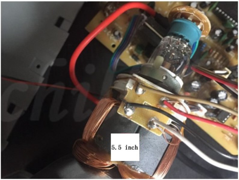
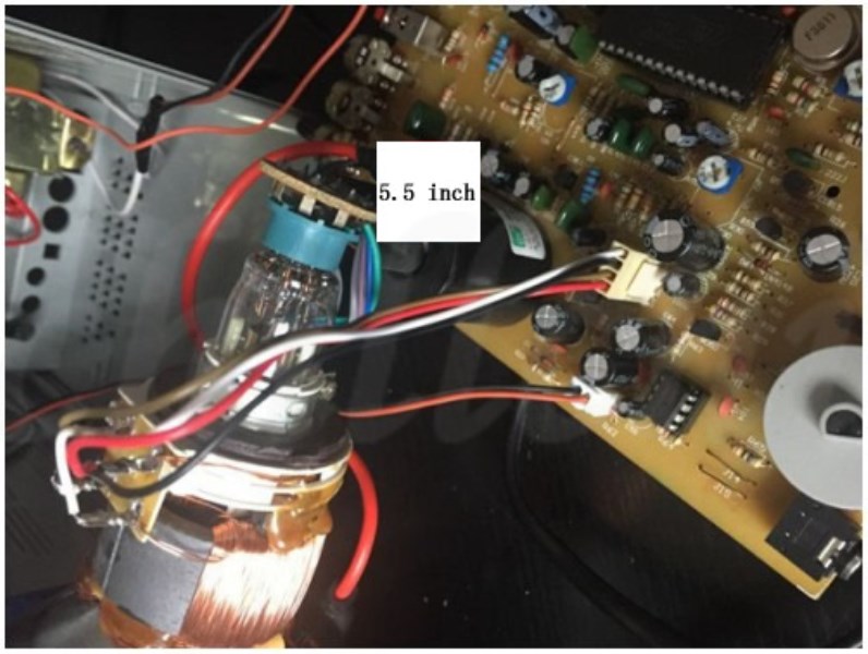
Five, welding and installation?Please see the figure below for wiring:
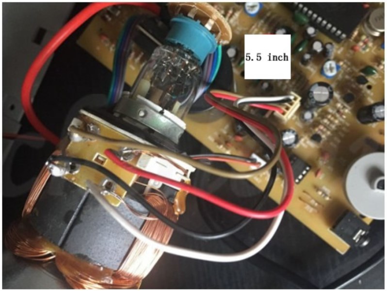
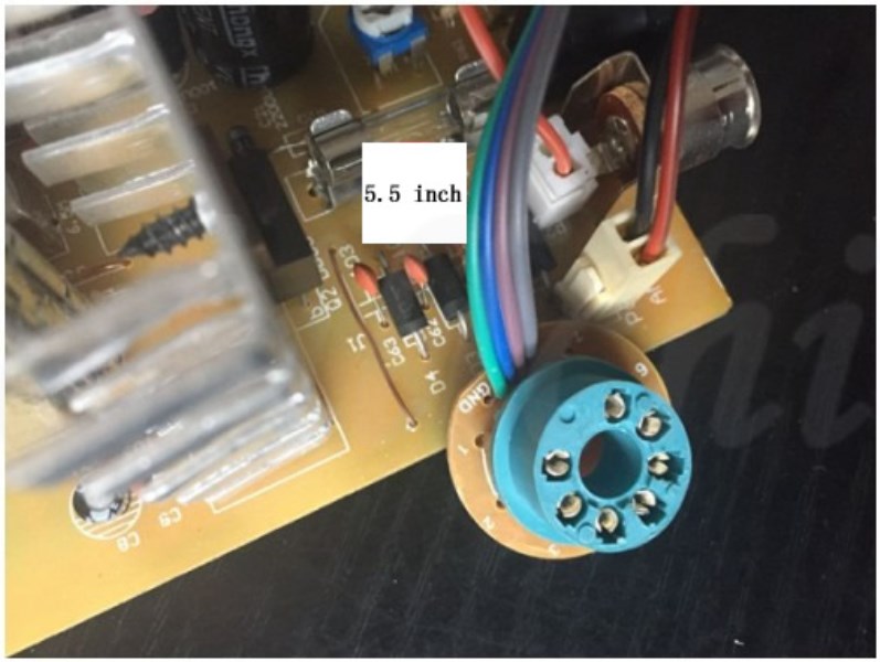
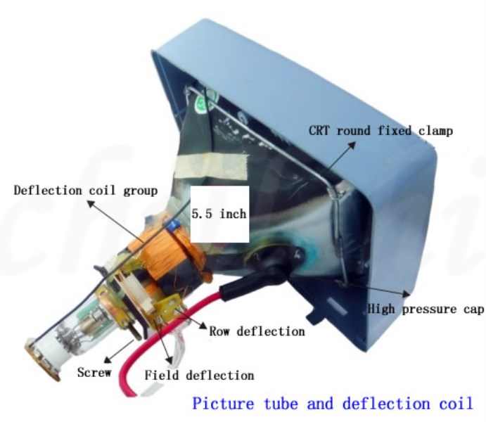
Picture tube and deflection coil:
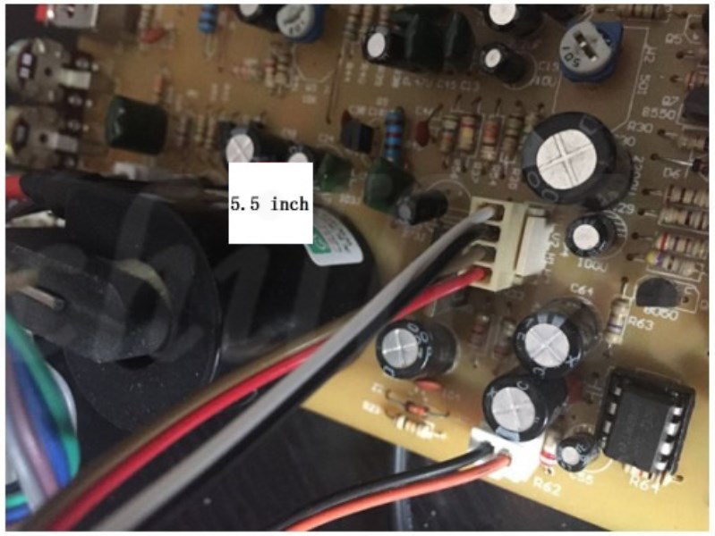
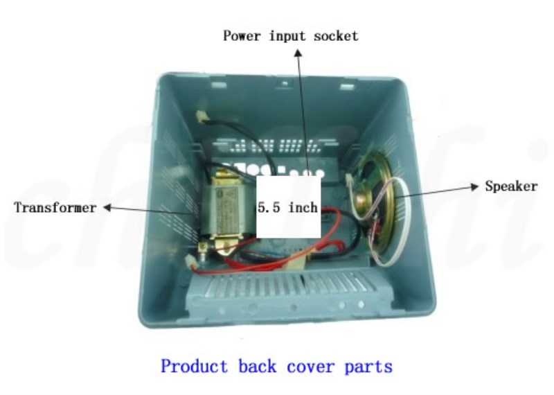
Internal components of the back cover:
 Six, debugging and final assembly