Brand Name:icchipcn.com
Condition:New
Type:Logic ICs
System transmission accuracy:±0.2%×F·S
Working temperature:0~60
Current output allows external loadimpedance:
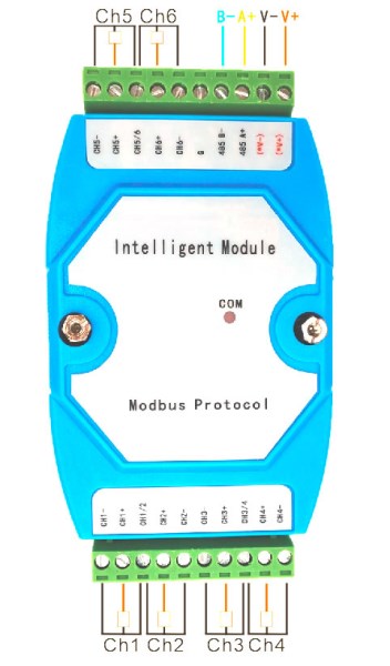
485 communication
Power supply:DC: DCtwenty fourV±10% V; or customized 12VDC and other power supplies
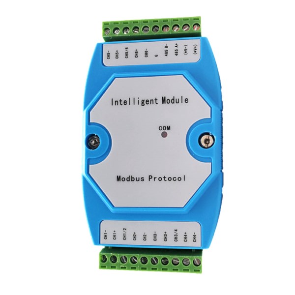
Dimensions:35mm standard guide rail..73mm wide*125mm high*43mm deep
Input signal type
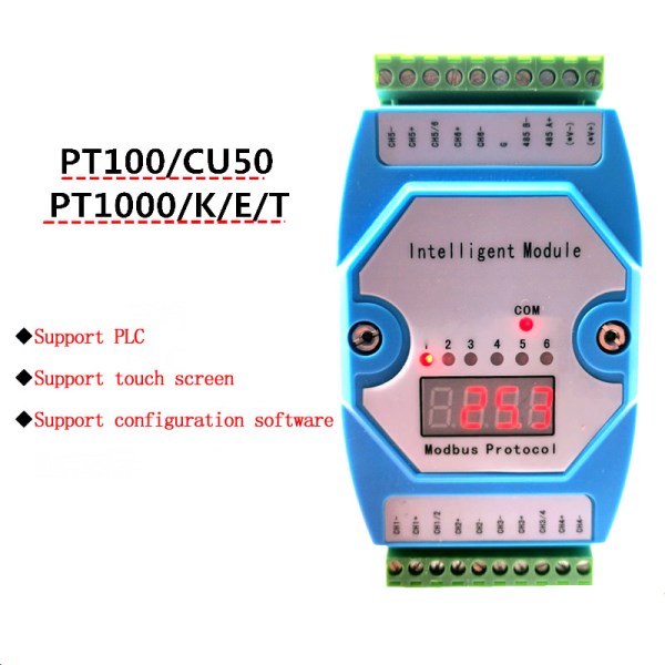
Thermal resistance: Pt100 standard
Pt1000Other inputs,Thermocouple:K,E,S,B,J,R,N,T
This communication protocol adopts the standard Modbus protocol, and the transmission mode used isRTUmode.ModbusAgreement is a master-Follow-up agreement.
Only one device can send on the wire at any time.The information exchange is managed by the master station, and only it can initiate it. It will poll the slaves one after another. Unless approved by the master station, no slave station can send messages. Direct communication between slave stations is not possible.
The protocol frame does not contain any message header byte or message byte terminator.
It is defined as follows:
Slave address | Request code | data | CRC16 |
Slave address:-Address must be at1To247between.
-Each address must be unique in the network device environment.
Data: Transmitted in binary code.
CRC16: Cyclic redundancy check parameters.
When the interval time is longer than or equal to3.5When the character is detected, it is regarded as the end of the frame detected.
1, Communication port settings
communication methodAsynchronous serial communication interface, such asRS-485,RS-232,RS-422Wait
Baud rate2400, 4800,9600, 19200bps(The instrument parameters can be changed mutually, the default is 9600)
2, Byte data format
.A start bit
.Eight data bits
.One stop bit
.No verification
1start bit8 data bits1stop bit
3. Instrument communication frame format
The following table is given byWhen the company's digital display is working in slave modeofModbusFunction and specify its limit.
Slave number:NativeInstrument address,Address must be at1To247The address of each instrument on the same bus cannot be repeated.
When the address is 0, it is used for the broadcast function, and only the write function is valid at this time. Single byte.
Function code:The "read" and "write" functions are defined from the perspective of the master. Single byte.
Function code | Modbusname | Function name |
| One time consecutiveNThe maximum |
3(0x03) | Read Holding Registers | Read N register values |
| 24 |
6(0x06) | Write Multiple Registers | Write 1register value |
| 1 |
First register address:The address of the first internal register to be read. Double byte.EachInternal registerThe value data of is double bytes.
Number of registers:The number of internal registers to be read or modified. Double byte.
Number of bytes read:The total number of bytes of internal register data read. Single byte.
CRC16:Cyclic redundancy check parameters.
1)readNOutput words: function3
note:Hi=High byte,Lo =Low byte.
This function can be used to read parameters regardless of the type.
Master request
Slave number | 0x03 | First register address | Number of registers | CRC16 |
Hi | Lo | Hi | Lo | Lo | Hi |
1byte1byte2byte2byte2byte
Slave response
Slave number | 0x03 | Number of bytes read | First register value | ... | Last register value | CRC16 |
Hi | Lo |
| Hi | Lo | Lo | Hi |
1byte1byte1byte2byte2byte2byte
example1:Use function3Read slave1Up1Words (address0003H,See Schedule)
Master request
0x01 | 0x03 | 0x00 | 0x03 | 0x00 | 0x01 | 0x74 | 0x0A |
1byte1byte2byte2byte2byte
Slave response
0x01 | 0x03 | 0x02 | 0x00 | 0x11 | 0x78 | 0x48 |
1byte1byte1byte2byte2byte
2)Write 1 output word: function 06(0x06)
Standard modbus write instructions
3)Abnormal response
When the slave cannot perform the request sent to it, it will return an exception response.
The format of the exception response:
Slave address | Response code | error code | CRC16 |
Lo | Hi |
1byte1byte1byte2byte
Response code:Function code requested+0x80(The highest bit is set to1). (Read: 0x83; write 0x90)
error code:
1 =The register address to be accessed in the request is not within the register address range.
2=The data exceeds the maximum value. (Shaping start address+Max11; Floating point is5)
3=The slave station is write-protected, and the LCK flag bit needs to be modified to unlock it.
4=The data exceeds the data range.
meterCorresponding address table of internal parameters (range: 0--161):
The address table corresponding to the internal
parameters of the instrument (range: 0--27):
No. | Parameter
symbols | parameter name | Register address | Data type | Type | Value range |
|
1 | NAME | Manufacturer
code | 0x0000 0 | 2 bytes unsigned | Read only |
| Spare |
2 | INP | Measurement type | 0x0001 1 | 2 bytes unsigned | Read/Write |
| Pt100 为9,不可修改 |
3 | DP | Spare | 0x0002 2 | 2 bytes unsigned | Read/Write | 1 |
|
4 | PS1 | Channel 1 offset | 0x0003 3 | 2 bytes unsigned | Read/Write | -1999~9999 |
|
5 | PS2 | Channel 2 offset | 0x0004 4 | 2 bytes unsigned | Read/Write | -1999~9999 |
|
6 | PS3 | Channel
3 offset | 0x0005 5 | 2 bytes unsigned | Read/Write | -1999~9999 |
|
7 | PS4 | Channel 4 offset | 0x0006 6 | 2 bytes signed | Read/Write | -1999~9999 |
|
8 | PS5 | Channel 5 offset | 0x0007 7 | 2 bytes signed | Read/Write | -1999~9999 |
|
9 | PS6 | Channel 6 offset | 0x0008 8 | 2 bytes signed | Read/Write | -1999~9999 |
|
10 | K1 | Channel 1
coefficient | 0x0009 9 | 2 bytes signed | Read/Write | 10~9000 | 1000 corresponds
to 1.000 |
11 | K2 | Channel 2
coefficient | 0x000A 10 | 2 bytes signed | Read/Write | 10~9000 |
|
12 | K3 | Channel 3
coefficient | 0x000B 11 | 2 bytes signed | Read/Write | 10~9000 |
|
13 | K4 | Channel 4
coefficient |
Q1: What Is Your Product Warranty?
A: We Guarantee Our Product Is Fit For Its Normal User Purposes And Is Free From Defects In Materials Or Workmanship.
Q2: What Is Your Company Policy On Defective Goods?
A: Our Company Keep Items Quality For A Long Time. If There Are Any Defective Goods Due To
Production Defects Or Transportation Problem, Please Contact Us. Our Customer Service Team Will Provide Immediate Response To
Complaints. We Will Try Our Best To Give You A Good Resolve Way.
Q3: What Is Your MOQ (minimum Order Quantity)?
A: Generally Our Moq Is No Limited. Please Have More Discussion With Us If Your Combination Of Models Is Complicated.
Q4:how About Getting Samples From You?
A: We Will Send You The Samples After We Receive The Payment For Samples. The Buyer Shall Afford The Shipping Cost. Please Have A
Confirm With Us Which Shipping Way Do You Want.
Q5:about The Shipment: What Type Of Shipment Will You Use?
A: We Usually Ship The Products By Express(delivery It To Your Door) Or By Air Freight To Your Nearest Airport, Shipping Days:3-7
Working Days Depend On Destination;if The Order Quantity Is Large, We May Ship By Sea Container And The Best Ship Way Is By Sea,
Shipping Days: Over 20 Working Days Depend On Destination Port.
Q6:what Packing Do You Use?
A: Neutral Package With Airbag Or Customized Package.
Q7:how Much Are The Shipping Cost?
A:shipping Cost Is Charged By The Package's Weight And Related To The Shipping Methods You Choose And Your Destination.
Q8:how To Order?
Step1.Click (Add to Cart) Buy Directly On The Product Page, Or Add To Shopping Cart And Settle Together, Pay With Paypal,
Need your information, such as full name,country, city, detail address, post code, tax number ...
Step2. We Will Delivery by EMS POST, FedEx or DHL Within
3-5 Working Days After Payment Confirmed.
Setp3. Confirm Us Receipt of Products.
|