Condition:New
Type:Logic ICs
15mm:Active input
20mm:Dry contact input
Chapter 1 product introduction
OneSummary
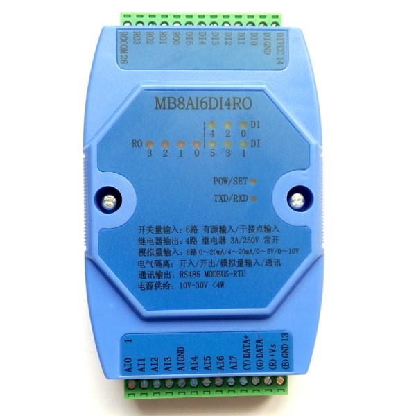
MB8AI6DI4RO 8The analog signal acquisition module can collect 8 analog signals of 0-20mA, 4-20mA, 0-5V and 0-10V. Each input port signal type can be set by software without jumper. It can collect signals of six trunk or wet nodes (active or passive input); as input of dry contact or sensor (NPN or PNP), it can set jumper common positive or negative input; as active input, it can automatically convert polarity without jumper switch; and four relays can be controlled by MODBUS bus. Modbus-RTU communication can be directly adapted to PLC, DCS and various domestic configuration software.
Signal acquisition, power supply and RS485 communication electrical signals are isolated from each other, effectively suppressing all kinds of serial mode and common mode interference, ensuring the accuracy of data, but also ensuring the reliable work of the module.
Two.Characteristic
1.The Modbus-RTU protocol is adopted.
2.Analog input can set the input signal type of each channel according to its own needs, only need software settings, without jumping line..
ThreeIt integrates 6 trunk connections or wet node signals (active or passive input) and 4 relay outputs.
4.Signal acquisition, power supply, RS485 communication, electrical signals are isolated from each other.
FiveRS485The communication signal output interface adopts over voltage and over current double protection.
SixThe input signal type and communication format can be set by software.
7.Power polarity protection.
Three.Technical indicators
project | parameter |
Analog quantity Signal input | 1Input channel: 8 channel isolation acquisition 2Signal types: 0~20mA, 4~20mA, 0~5V and 0~10V four analog signals. 3Sampling rate: 200HZ(each channel)Twenty-fivesecond/Seconds) 4Resolution:12bit FiveAcquisition accuracy: voltage input 0.2% current input 0.3% 6. ADAcquisition circuit and CPU isolation voltage protection: 1500V |
Switch quantity Signal input | 1Input channel: 6 trunk contact or wet node switch input. 2Signal type: CO positive or co negative input, polarity automatic recognition. 3Signal level: high level (10V ~ 30V) low level (0V ~ 1V) FourSampling rate: 1000HZ FiveIsolated voltage protection: 1500V |
Relay signal output | 1Output channel: 4 way normally open relay output. 2Load capacity: resistive load 250V/3A inductive load 250V/1A FiveIsolated voltage protection: 1500V |
Communication output | 1Communication protocol: MODBUS-RTU 2Interface type: isolated RS485 communication, output interface adopts over voltage and over current double protection. 3Baud rate: 1200BPS, 2400bps, 4800bps, 9600bps, 19200bps 4Check bit: no check, parity check, odd check. 5Setting mode: module address, baud rate, parity bit can be set by software. 6Communication distance: 9600bps 1200 meters. SevenRS485Communication circuit andCPUIsolated voltage protection:1500V |
Module size | A.Single module size: 104mm*72mm*26mm B.Terminal and guide box size: 124mm*72mm*45mm |
Installation method | standardDINDIN-Rail Mounting(35mmGuide rail or high and low guideway) |
work environment | Temperature: -10 ~ +55 C humidity: 35~85% (no condensation). |
Working power supply | 1Power supply voltage: 10V~30V wide range of power supply, polarity protection with power supply 2Power consumption: less than 3W |
Four.Product appearance and peripheral wiring diagram
Five.Function description of module indicator lamp
1.POW/SET;Module work status indication
A.The green light is always bright: the module works in the running state B. the red light is always bright: the module works in the configuration mode.
2.TXD/RXD:Communication status indication
A.Green light: communication receives data B. red light flashes: module is sending data.
C.The green light is always bright: the communication RS485 line on DATA+ and DATA- is reversed or the connection is broken.
Six.Module right switch function description
1.Operating mode: switch to the top, and then the module power is re-energized; the module works normally in this mode, this mode can not configure the working parameters; the communication parameters of working mode are set by users, default communication parameters of factory (address: 1, baud rate: 9600 bps, check bit: no, stop bit) The 1 digit).
2.Configuration mode: switch to the bottom, and then the module power is re-energized; used to view or set module communication parameters, analog input and analog output parameters, mode communication parameters are fixed (address: 1, baud rate: 9600 bps, check bit: no, stop bit: 1 bit).
Seven.Terminal definition
terminal | Name | Explain |
| terminal | Name | Explain |
1 | IN0 | Analog input channel 0 | 14 | DIVCC | Switch input power supply positive pole |
2 | IN1 | Analog input channel 1 | 15 | DIGND | Switch input power supply negative pole |
3 | IN2 | Analog input channel 2 | 16 | DI0 | Switch input 0 |
4 | IN3 | Analog input channel 3 | 17 | DI1 | Switch input 1 |
5 | AIGND | Analog input common end | 18 | DI2 | Switch input 2 |
6 | IN4 | Analog input channel 4 | 19 | DI3 | Switch input 3 |
7 | IN5 | Analog input channel 5 | 20 | DI4 | Switch input 4 |
8 | IN6 | Analog input channel 6 | 21 | DI5 | Switch input 5 |
9 | IN7 | Analog input channel 7 | 22 | RO0 | Relay output 0 |
10 | DATA+ | RS485Communication + | 23 | RO1 | Relay output 1 |
11 | DATA- | RS485Communication - | 24 | RO2 | Relay output 2 |
12 | +Vs | Power input + | 25 | RO3 | Relay output 3 |
13 | GND | Power input - | 26 | ROCOM | Relay output common end |

