Type:Logic ICs
Condition:New
8DI/8DO:Isolated acquisition and control module of digital input and output
Input type:8 way digital input
type of output:The output drive current of the 8 way isolation transistor is up to 1A
Communication type:MODBUS-RTU RS485
Characteristic:Signal acquisition, RS485 communication, dry contact isolation input
A chapter of product introduction
First, product overview
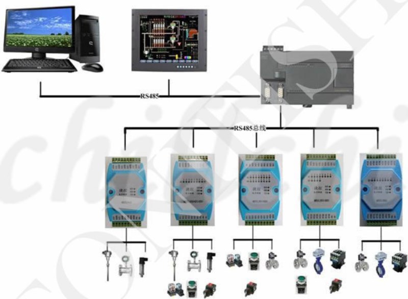
MBSL8DI8DOThe module is a 8 channel digital isolation input and a 8 channel digital isolation output (NPN transistor collector open output) module, which is output by isolating the RS485 interface. The module adopts standard Modbus RTU communication, and can directly accommodate all kinds of upper computer configuration software, PLC, DCS, etc. Module power supply, RS485 communication and electrical signals are isolated from each other, effectively suppressing all kinds of series mode and common mode interference, as well as ensuring the stable and reliable operation of the module.
1,The RS485 MODBUS RTU standard communication is used for networking with PC configuration software, PLC, industrial touch screen, etc.With a communication state indicator.
2,Industrial standard:Signal control, power supply, RS485 communication, electrical signals are isolated from each other.
3The communication circuit adopts lightning protection, anti-jamming design,Power polarity protection.
4RS485 communication signal output interface adopts over voltage and over current double protection.
5It can be widely used for signal acquisition and control in industrial field equipment.
6The communication format can be set by software.
7, module adoptionHardware and software double watchdog timerVehicle grade standards ensure that modules never fail and work stably and reliably.
8.Output fault network protectionWhen the 485 network interrupts, when the machine does not receive the data sent by the main station in the set time, the module will automatically disconnect the output, thus automatically protecting the safety of the field equipment.
Two, the main technical indicators
Project | Technical indicators |
Signal input / output | 1Input channel: 8 channel digital isolation input 2Output channel: 8 way digital quantityquarantineoutput 3Load capacity: resistive load 1A/ channel |
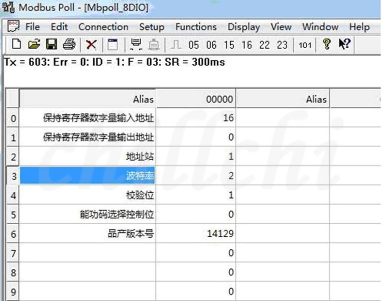
Communication output | 1Communication protocol: MODBUS-RTU 2Interface type: isolated RS485 communication, output interface adopts over voltage and over current double protection. 3Baud rate: 4800bps, 9600bps, 19200bps, 38400bps, 57600bps 4Check bit: no check, parity check, odd check 5Setting mode: module address, baud rate, parity bit can be set by software. 6Communication distance: 9600bps 1200 meters |
Module size and installation method | 1. Installation: Standard DIN guide rail installation or screw installation. 2,Shape size: 125 x 73 x 35mm |
work environment | Temperature: -10~+60 CHumidity: 35~85%(non - condensation) |
Working power supply | 1Power supply voltage: 10V to 30V wide range of power supply, polarity protection with power supply 2Power consumption: less than 3W |
Three. Interface definition
Terminal name | say bright | Terminal name | say bright |
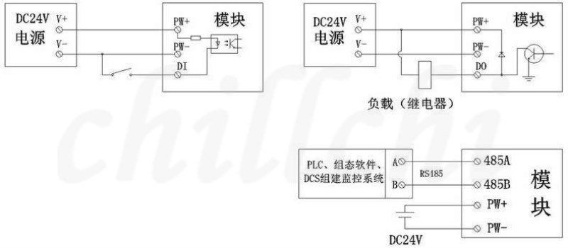
PW+ | External power input positive end | 485A | RS485Signal A+ |
PW- | External power input negative end | 485B | RS485Signal B- |
DI1 | Digital input channel1 | DO1 | Digital output channel1 |
DI2 | Digital input channel2 | DO2 | Digital output channel2 |
DI3 | Digital input channel3 | DO3 | Digital output channel3 |
DI4 | Digital input channel4 | DO4 | Digital output channel4 |
DI5 | Digital input channel5 | DO5 | Digital output channel5 |
DI6 | Digital input channel6 | DO6 | Digital output channel6 |
DI7 | Digital input channel7 | DO7 | Digital output channel7 |
DI8 | Digital input channel8 | DO8 | Digital output channel8 |
Four.Module wiring diagram
Five. Communication instructions
1Communication parameters description (factory value):9600, N, 8, 1
parameter | Explain |
9600 | baud rate |
N (No check) | Checkout bit |
8 | Data bit |
1 | Stop position |
The second chapterModbusRegister and communication protocol description
1.Module supported MODBUS function code and address range
1Module supported MODBUS function code
Register type | Address range | Function code | Function code description | Operation |
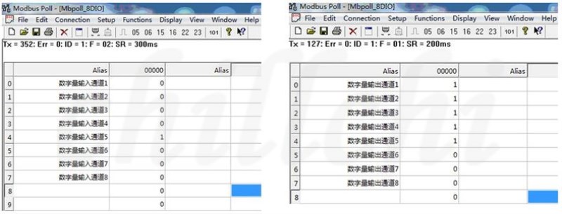
Output coil register | 00001-00008 | 0x01H | Read multiple coil registers | Read the values of one or more coil registers |
0x05H | Write a coil register | Write the value of a coil register |
0x0FH | Write one or more coil registers | Write the value of one or more coil registers |
Hold register | 40001-40016 | 0x03H | Read multiple hold registers | Read the values of one or more hold registers |
0x 06H | Write a single hold register | Write a data to the hold register |
0x 10H | Write multiple hold registers | Write one or more data to the hold register |
Input digital quantity | 10001-10008 | 0x02H | Read input discrete quantity | Discrete-time input register |
Two. Register definition description
1.Output coil register (function code:0x01H,0x05H,0x0FH)
address | parameter | length | read/write | MIN | MAX | Explain |
00001 | DO1 |

