Type:Logic ICs
Condition:New
Freight number:WS-4/12/32
There are 5 LED digital display on the motherboard. There are three display formats.


- ----
0C 22.3
1H 67.2
The first display means that the 4 channels are not connected to the sensor.
The second display means the sensor temperature on channel 0.CIt's 22.3Centigrade
The third way of display is the humidity of the sensor on channel 1.HIt's 67.2%
The description of the LED digital tube display process:If the system is running, if there are no sensors on the 4 channels, it will show "-".If there are sensors in channel 2, the temperature and humidity of channel 2 are displayed alternately every 1.5 seconds, such as "2C 26.5" and "2H 70.8", indicating that the temperature of channel 2 is 26.5.CentigradeThe humidity is 70.8%;If more than one channel is connected to the sensor, the temperature and humidity of each channel are displayed alternately every 1.5 seconds, starting again and again.
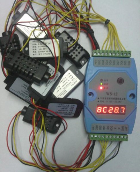
The 6 bit LED digital tube in the top picture shows a lack of one, because the 6 bit LED digital tube is scanned by scanning, and the digital camera is not fully captured by 6, and the real eye sees 3C----.
The following is a physical picture of the 12 channel collector when it is full of AM2301 sensors. Please refer to it.
4 channelconnectionExplainThe following diagram* * * * * * * * * * * * *
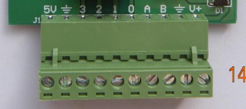
As shown above, each temperature and humidity sensor leads to three lines: the red is +5V, the Yellow data line, the black ground wire!!! When the 4 road sensors on the temperature measuring board are full, 4 red lines are pinched together to connect 5V; the 4 black lines are pinched together to connect the ground line; the 4 yellow lines are connected to the 4 passages of the labeled 0~3. Don't tell me that I don't know which is the ground line.
As shown in the figure above,Terminal terminalThe left label 3~0 indicates the temperature and humidity sensor channel 3~ channel 0.Each channel can only be connected to one sensor, that is, to connect the sensor to three lines.yellowLineB A represents the 485 interface signal line; 5V is the DC5V power output from the collector, which is used to connect the positive and negative power lines of the temperature and humidity sensor.That is, in the three line of the sensorredLine24V is the power input to the collector, the input voltage range of which can be DC12 ~ 24V; there is also a ground wire, located in the second right terminal position. 4 channel sensorblackThe color lines should be connected to the ground line.
For the 12 channel and the 32 channel collector, besides the number of sensor channels, other wiring modes are the same.
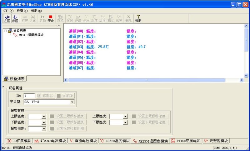
The following are the communication protocols and related contents.Free of chargeManagement software screenshot:
By reservation485 interfaceSpecialDesigned for embedded applicationsA temperature collection interface board, which has been applied to a large number of customers for a long time and the strong technical support of my hardware and software, has begun to use embedded applications for customers.Batch matchingWe are gradually increasing the popularity of similar products in Taobao network. I dare not say that it is the most excellent one. But please use it boldly and safely. If you do not believe it again, please go through the comments and comments of the buyers, say no more, please look at the introduction of the product!!!!
Mechanical size:31.5x58mm
Installation aperture: 3.2mm
Center distance of installation hole: 49.3x26.1mm
Sensor: AM2301
Sensor line length: 30CM, can be extended to 20 meters
Range of temperature measurement: -40Centigrade~80Centigrade
Humidity measurement range: 0%~100%
Temperature and humidity resolution: 0.1 C /0.1%
Power supply: DC 12V ~ DC24V
Communication interface: RS485
Data format: 9600,8, N, 1
MODBUS RTU communication protocol introduction:
Read from the temperature and humidity sensor data from the machine
For example:The 485 bus has been attached to oneWS-4typeThe temperature and humidity acquisition board, ID is 01, a total of 4 sensor channels, read all 4 channels of sensor data.
The message format sent by the host:
send content | Bytes | send data | Remarks |
Slave address | 1 | 01H | Slave address |
Function code | 1 | 03H | Read register |
Start register address | 2 | 01F4H | 01F4H - this register saves sensor channel 0 temperature value. 01F5H - this register stores the humidity value of sensor channel 0. Yes. 01FAH - this register saves sensor channel 3 temperature value. 01FBH - this register stores the humidity value of sensor channel 3. The above 8 register addresses are located[4]area |
Read word length | 2 | 0008H | read8 words (16 bytes) |
CRC check | 2 | XXXXH | All the previous dataCRC code |
Description: from the machine to the specified register addressAt first, according to the number of words returned by the host, the data in the register is uploaded in sequence.
Message format returned from the machine:
send content | Bytes | send data | Remarks |
Slave address | 1 | 01H | No. 01Slave machine |
Function code | 1 | 03H | Read register |
Return byte length | 1 | 10H | Return to 16Temperature and humidity data in bytes |
Return data | 4 | FF83H 019CH 00B0H 0308H . 00B1H 0309H | Sensor channel0 temperature -12.5 C Humidity 41.2% Sensor channel1 temperature and 17.6 degrees centigrade Humidity 77.6% Yes. Sensor channel3 temperature and 17.7 degrees centigrade Humidity 77.7% |
CRC check | 2 | XXXXH | All the previous dataCRC check |
Return data format specification: each sensor channel is uploaded in order of temperature and humidity.Two words, each of which is a double-byte signed integer, converted into decimal, just 10 times the sensor's actual measurement value.
In order to facilitate the two development, the buyer must be familiar with the communication protocol above, and through the master software developed by the owner of the store, the original data and module communication can be easily sent manually, such as you need the software,Free gift!
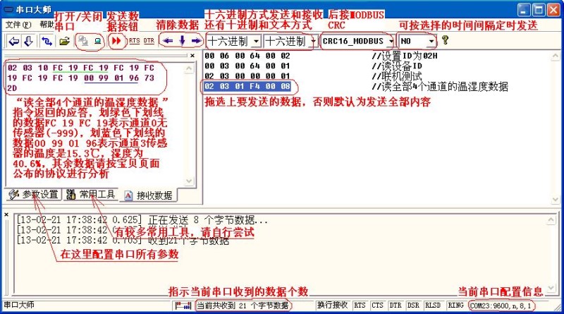
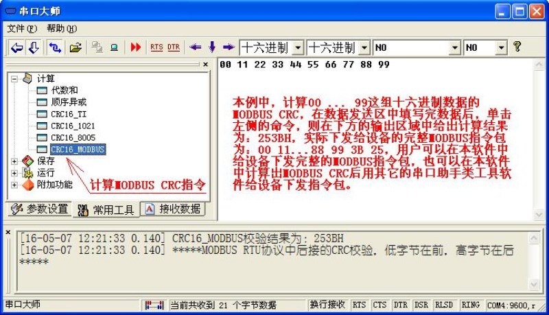
Users can also use other familiar serial assistant class software to test, but send
The MODBUS instruction package must be connected to the MODBUS CRC of 2 bytes, which is provided by the software.
Calculate the function of MODBUS CRC, the screenshot is as follows:
The test data of this module are as follows:
010301 F4 0004 / / read the temperature and humidity data of all 4 channels.
End

