Brand Name:icchipcn.com
Condition:New
Type:Logic ICs
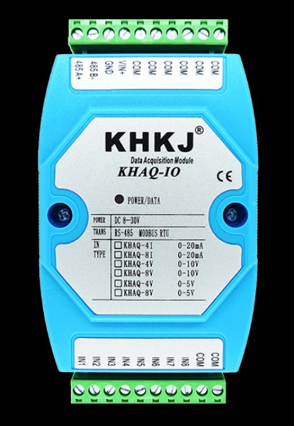
Analog input acquisition module 8 4-20mA isolated RS485 MODBUS RTU
Product Feature:
Product name: 8-channel analog quantity acquisition module
Input type: channel can be connected to 4-20MA, 0-20MA signal
Wire type: active, passive, two-wire, three-wire, four-wire
Communication standard: isolated RS485, standard MODBUS communication
Communication format: device address 1, 9600, N, 8, 1 (default), the baud rate and calibration can be set quickly and easily through the software
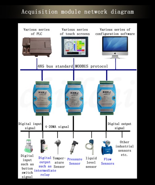
Support equipment: PLC, touch screen, Kingview, force control, LABVIEW and other configuration software
Working voltage: DC8-30V (24V recommended)
Working temperature: -40℃- +85℃
Product size: 122*72*43MM (length * width * thickness)
Installation method: standard 35M rail installation
Accuracy: 16 bits, high-precision measurement
485A+: RS485 serial communication A
485B-: RS485 serial communication B
GND: DC power negative pole
VIN+: DC power positive pole
COM: Common terminal of the sensor, internally shorted
to GND
NC: Null side, meaningless
INx: sensor data input
Wiring
The module supports two-wire, three-wire, four-wire 4-20mA,0-10V sensors, transmitters; or other current and voltage signal sources.
Two-wire passive transmitter wiring method: The two-wire transmitter has only two wires, and the power supply and signal are shared. 24V+ is connected to the transmitter+, and the transmitter- (also called signal output) can be connected to the IN input of the Kunhang module. This forms a loop because the module COM and 24V- are internally shorted.
Three-wire transmitter wiring method: 24V+ is connected to the transmitter+, 24V- is connected to the transmitter-, and the signal output of the transmitter is connected to the IN terminal.
Four-wire transmitter wiring method: 24V+ is connected to the transmitter+, 24V- is connected to the transmitter-, the transmitter signal output+ is connected to the IN terminal, and the transmitter signal output- is connected to the COM terminal.
Function Codes and Register Addresses
Module default device address 1,9600, N, 8, 1
1、Function code 03H (read)
Input register information table (read-only property)
Hexadecimal address | Decimal address | Description | Parameter Description | Attributes |
|
|
|
|
|
|
|
|
|
|
|
|
|
|
60H | 40097 | Channel 1 analog input value |
| R |
|
|
|
|
|
|
|
61H | 40098 | Channel 2 analog input value |
| R |
|
|
|
|
|
|
|
62H | 40099 | Channel 3 analog input value | The
value is a 16-bit signed integer: -32768 - 32767, the unit is: uA, mV The
read data divided by 1000 is the real mA, V value. | R |
|
|
|
|
|
|
|
63H | 40100 | Channel 4 analog input value |
| R |
|
|
|
|
|
|
|
64H | 40101 | Channel 5 analog input value | For
example: read data 8000, means 8000 (uA, mV) Equivalent
to 8.000 (mA, V). | R |
|
65H | 40102 | Channel 6 analog input value |
| R |
|
66H | 40103 | Channel 7 analog input value |
| R |
|
|
|
|
|
|
|
67H | 40104 | Channel 8 analog input value |
| R |
|
Module Data Conversion Formula
4-20mA corresponds to the collected digital quantity of 4000-20000, and the conversion formula is as follows:
y=(collected digital quantity-4000)*(upper limit of engineering quantity-lower limit of engineering quantity)/16000+lower limit of engineering quantity
Where: y is the calculated engineering quantity value. For example, 4-20ma corresponds to 0-150℃. Use our module to collect, apply the above formula as follows:
y=(collected digital quantity-4000)*(150-0)/16000+0
0-10V corresponds to 0-10000, and the conversion formula is as follows:
y=(collected digital quantity-0)*(upper limit of engineering quantity-lower limit of engineering quantity)/10000+lower limit of engineering quantity
Where: y is the calculated engineering quantity value. For example, 0-10V corresponds to 0-150℃. Use our module to collect, apply the above formula as follows:
y=(collected digital quantity-0)*(150-0)/10000+0
Code Comments
1. The module follows the standard Modbus Rtu protocol. The following explains how to send and receive commands and how to read the value of the channel.
2. For module sending within 16 channels (including 16 channels):
Note: 01 is the station number. 03 is the function code. 00 60 is the starting address of the register of the read module (00 is the upper eight bits, 60 is the lower eight bits). 00 10 is the number of registers to be read (00 is the upper eight bits,10 is the lower eight bits). 44 18 is CRC check (the check user can check online data or have special CRC check software)
Receive: 01 03 20
00000000000000000000000000000000000000000000000000000000000000 927a
Note: 01 is the station number. 03 is the function code. 20 is the number of bytes returned.
After 20, the data from No. 1 to No. 16 is followed in turn. Each channel occupies 2 bytes and is a 16-bit signed integer. The last two bytes 927a of the return code are the CRC check. The returned data is different, and the CRC
check is different. 3. For 32-channel acquisition module
Send:
For sending and receiving, please refer to the 16-channel internal module code.

