Type:Logic ICs
Condition:New
Model Number:AW07A
No.:AW07A
Decoration and construction contents:Hydropower project
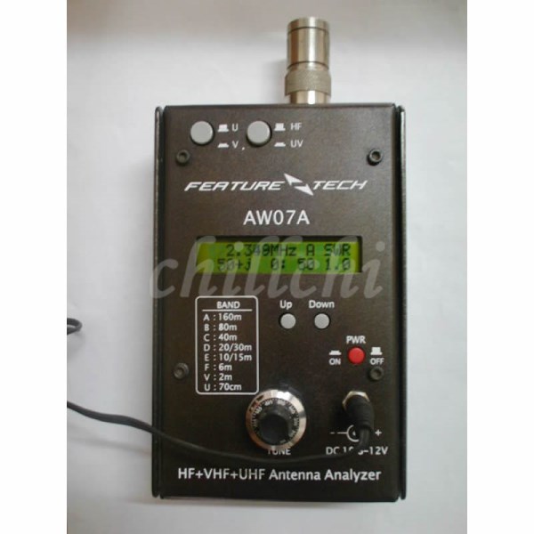
Antenna analyzer
An instruction manual
In addition to the antenna analyzer and radio frequency meter main functions, but also with capacitance and inductance measurement and estimation function, attached to its own simple detection coil circuit, but also has the function of trap immediately. 50 ohm antenna feed system for VHF amateur radio 160 until 70 cm wave band of the amateur and experimental testing and adjusting.
I. basic specifications
1. frequency range: 160M+HF+VHF+UHF (1.5-490MHz intermediate with a small amount of merchandise, but satisfies the continuous range of 1.6-56MHz and 135-175MHz and 400-470MHz)
2. output amplitude: open circuit peak value of about 2V.
3. standing wave value (SWR): test range 1~10.
4. compound impedance (Z): test range 10~500 euro.
5. power supply: external voltage 10.8~12.5V, load current 500mA or more DC regulated power supply, DC seat inside and outside the negative, built-in 8 section 5 battery clip. Recommended to use the built-in 10.8V lithium battery power supply, three groups consisting of weight; if you use the battery clip as far as possible the use of sealing alkaline battery 5 well. General rechargeable battery eight, minimum 9.6V, preferably in comparison test results, confirmed that no problems can also be used. Try to avoid higher than the 13V power supply, the UV segment circuit may be damaged due to excessive power consumption.
Consumption current: 10V experimental power supply, the switch is in HF band position, LCD backlight is closed, the maximum 150mA; backlight open maximum current 200mA. The UV bands are about 165 mA and 240 mA, respectively.
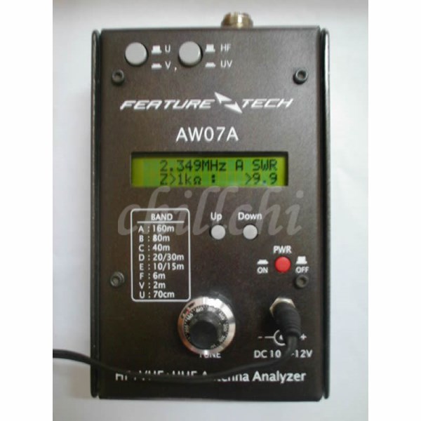
6. screen display: antenna interface, open circuit display, SWR>9.9, Z>1K. After entering the analyzer function, the first row of the screen displays frequency values, band switches, segmented letters, and Bobbi SWR, respectively, and the second row displays resistance Rj reactance: composite impedance Z and SWR values. The remaining display references are specified later.
Two, button and menu instructions
A power switch is PWR, Up, downlink uplink key key Down, UV band and HF band switch UV/HF, U band and V band U/V switch (the switch is effective only in the UV/HF Press) a total of five switch button and a frequency selection button TUNE and a combination of them to complete the test function. The following menu shows further instructions:
Boot function selection instructions
PWR: press this key to open a separate power analyzer, menu display designers call sign and backlight on key tips, immediately press the U button about half a second to open the backlight, if not press any key, delay one second automatically enter the frequency meter and antenna analyzer function selection menu.
In addition, if you press U or D key and then open the power into the inductance or capacitance test, this function because of the instrument to be measured and the effects of distribution parameters and testing ways of their components can only provide a reference value, not as a standard numerical basis, but can be very good for the antenna configuration of capacitor and provide the reference value of the inductor is convenient.
Up and Down: the corresponding abbreviations in the screen prompt are D and U respectively. After the boot, automatic stop to show D-FC, U-ANT, Analyzer, DC:XX.XXV, respectively, according to the D key select frequency meter function, press the U button to select the antenna analyzer function, and the latter is the power voltage estimation.
Frequency meter instructions
The frequency meter uses MHz as the unit, and the Fg indicates that the fast gate displays the 3 bit valid value after the decimal point. Sg indicates that the slow gate can display 4 effective values after the decimal point. Press the U and D keys for a moment to switch. The analyzer frequency meter after correction, but due to different reasons and the instrument signal measured waveform itself itself reference source instability may have errors, do not as a frequency standard basis, provide effective reference frequency but can detect unknown machine. The frequency meter is given the antenna reach high frequency voltage corresponding to the actual reference field REF FS test circuit values can predict the electromagnetic environment to the antenna induction of analyzer test results influence the irresistible, if the voltage is too high is not able to provide accurate test results, similar products have the same problem analyzer. The analyzer also has an antenna induced signal overvoltage alarm function to prevent damage to the machine.
Note: use frequency meter function, UV/HF switch must be in HF position, otherwise the screen shows FREQ.C SW, Error, PSE, VU/HF, SW, UP words, prompt UV/HF switch, please restore to HF position in time.
Instructions for use in antenna analyzers
Enter the analyzer function after the first row of the screen display value, frequency band switch and segmented letters, in Bobbi SWR words, second rows of open display Z>1K and SWR value of Omega >9.9 load connected to an antenna or working in the high-end frequency, respectively - resistance reactance of the +j: specific numerical composite impedance and SWR. In HF band, press U or D key to switch up and down the band of corresponding wavelength; press UV/HF to switch to VU segment, and work as UHF or VHF band depending on the position of U/V key.
UHF bands do not provide effective impedance values, and similar commodity analyzers do not provide effective impedance values. In addition to providing SWR values in the UHF segment, the AW07A provides an auxiliary signal strip corresponding to SWR less than 2.
Please turn TUNE and return to the correct frequency range. In the U segment, this analyzer provides test values of at least 300MHz to 490MHz, far exceeding the performance of expensive similar commodity analyzers in the U segment. If the same word appears in other bands, there may be a machine failure or a low power supply voltage. Please find out the reason in time.