Condition:New
Type:Logic ICs
Circuit board repair online tester instructions
One. The main technical parameters
Sine wave voltage | 5Vpp | |
Sine wave frequency range | Min20Hz,max15kHz | |
Source resistance | 500Europe | |
Trigger level | +5V | |
Input power supply voltage | 140-220v,50Hz | |
| | |
two. Firmware introduction
1.Output frequency selection button:
LOWPress to select low frequency,MEDIUMPress key to select IF,,HIGHTPress to select high frequency.
2.Banana socket
red,AChannel; blue,GTrigger; black commonCOM, Or toGND.
three.Instructions
1.debugging
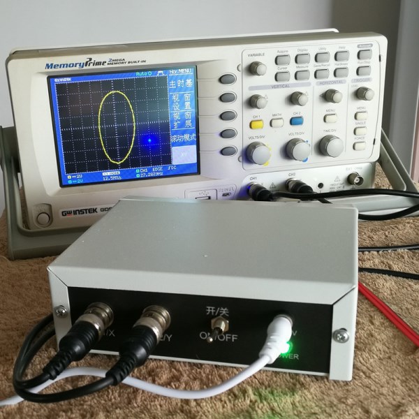
Plug in the power adapter, the testerX,YWith oscilloscopeX,YDocking (dual trace oscilloscopeX-CH1,Y-CH2),CH1,CH2SetDCCouplingAChannel meter pen, dual trace oscilloscope set inXYFile, single trace oscilloscopeT/DIVSet outX. When the power is turned on, the oscilloscope displays a horizontal line (if it displays a vertical line, it isXYConnected back,XYJust swap it. ) Adjust the oscilloscopeS/DIV,Make the lines clear and continuous, adjust the oscilloscopeXChannelVOLTS/DIV, Make the horizontal line length appropriate, (single-track oscilloscope is adjusted on the testerATTENUATIONAttenuation potentiometer), adjust the oscilloscope when the two test leads are short-circuitedYChannelVOLTS/DIV,Make the length of the vertical line appropriate. The commissioning is now complete.
2.Oscilloscope debugging method
(1)Analog oscilloscope
Turn the knob and switch toXYorX-Y, The oscilloscope displays a point, move the point to the middle, and enterCH1, CH2, DCCoupling, volts/grid2V, Then connect the tester, the oscilloscope displays a horizontal line, adjustCH1Fu/Grid button, make the horizontal line length suitable.
(2)Digital oscilloscope
enterCH1, CH2, DCCoupling, volts/grid2V, (Main) time base2ms-5ms,XYMode. How to enterXYMode, commonly used oscilloscopes have2Kind ofMANUKey; aDISPLAYkey
3.Experience
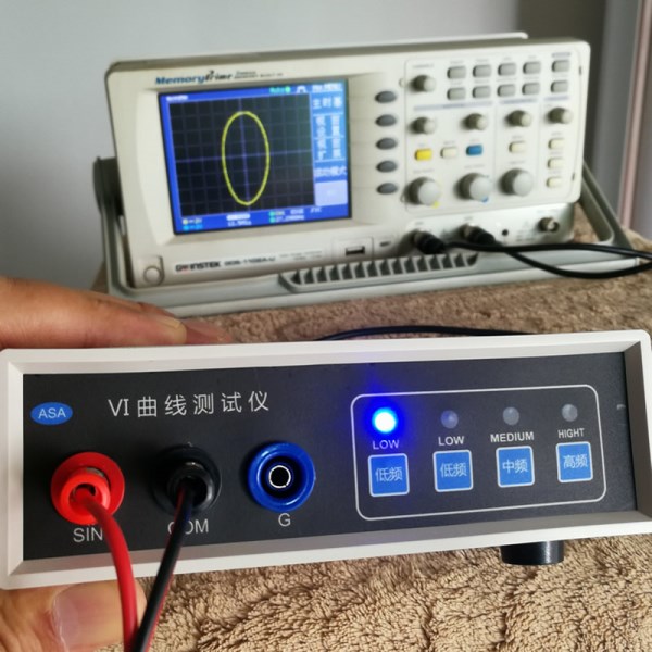
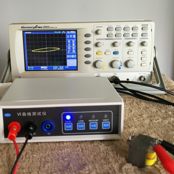
Circuit board repair online tester is a display on the oscilloscopeVIThe curve graph, the instrument that judges the device characteristics by graph comparison, is the extension of the multimeter, which is similar to the resistance file of the multimeter, except that the multimeter loads the DC voltage test device outwards, and the tester loads the AC voltage test device outwards to test the resistance function A vertical line indicates a straight-through, a horizontal line indicates an open circuit, and the resistance value is a diagonal line. Various curves are displayed for testing functions such as capacitance, inductance, semiconductor, and integrated circuit (the figure is omitted). The essence of the tester is "comparison",2One circuit board is good and the other is bad, and the fault can be found through comparison (of course, the success rate is not absolute, and experience value is required), so there is a legend that the circuit board can be repaired without a circuit diagram.
Generally speaking, the use of the tester is the same as the resistance profile of a multimeter. The device or circuit board under test cannot be charged. The red and black test leads are free to test.2point(2Foot) can be seen on the oscilloscopeVICurve graph, judge the fault point of the faulty device or circuit board according to the comparison of graphs, and judge the graph must be the same model2Device or circuit board2The same position point (the graphics produced by different manufacturers of the same type of device will be different, please note that this is not broken),According to the test capacitance, inductance, electronic transformer and other capacitance (inductance), choose different frequencies, small capacitance, and small inductance.MEDIUMorHIGHT,Large capacitance (inductance) is selectedLOWorMEDIUM, Test resistance, small resistance is vertical slash, the larger the slope, the smaller the resistance.
The key to the tester application isCompare, More than ever, more than the point of failure. There are device comparisons, circuit board point comparisons, and device and human brain memoryVIComparison of curves and graphics, so experience is very important. When comparing, the black test lead usually selects the deviceGND,Vss,Vdd, The red test pen test each point,2A circuit board must share a common ground, so the efficiency is high, of course, it can be arbitrary2point. For circuit boards that are often encountered, you can also test some curve graphics, take photos and save them for emergency needs.