Type:Logic ICs
Condition:New
I. Product Overview
l 8Opto-isolated digital inputs and 8 opto-isolated digital outputs (NPN open collector transistor output )
l Using RS485 MODBUS RTU standard communication , networking and configuration software can be , PLC, industrial touch screen , etc.
l With communication and input and output status indicator
l Communication circuit lightning , anti-jamming design
l Signal acquisition and control can be widely used in industrial field devices
l Normal use of three-year warranty
Second, the main parameters
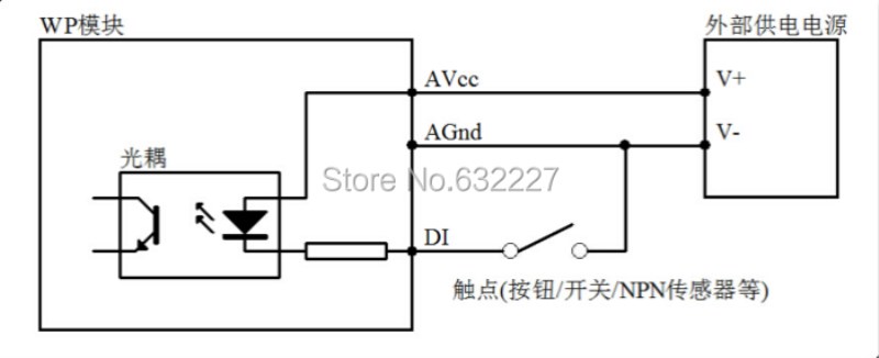
l 8 digital input channels (active low )
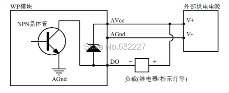
l 8 digital output channels (NPN transistorOpen collectorOutput ,500mA)
l Operating temperature range -20 ~70
l External power supply DC 9V ~30V / 2W
l 1500VDC isolation protection
l Standard DIN mounting rail or screw mounting
l Dimensions 125 × 73 × 35mm
Third, the interface definition
| AVcc | The positive terminal of the external power input |
| AGnd | Negative external power input terminal |
| DO_01 | The first digital outputs |
| DO_02 | The first two digital outputs |
| DO_03 | 3 digital outputs |
| DO_04 | 4 digital outputs |
| DO_05 | 5 digital outputs |
| DO_06 | 6 digital outputs |
| DO_07 | Section 7 digital outputs |
| DO_08 | Section 8 digital outputs |
| DI_01 | The first digital inputs |
| DI_02 | The first two digital inputs |
| DI_03 | The first three digital inputs |
| DI_04 | 4 digital inputs |
| DI_05 | 5 digital inputs |
| DI_06 | 6 digital inputs |
| DI_07 | The first seven digital inputs |
| DI_08 | The first eight digital inputs |
| 485A | RS485Signal A + |
| 485B | RS485Signal B- |
Fourth, the digital application diagram
1, Digital input application
2Digital output applications
Five , communications instructions
1,Communication Parameters ( factory default ): 9600, N, 8,1
| Parameters | Description |
| 9600 | Baud Rate |
| N (No parity ) | Parity bit |
| 8 | Data bits |
| 1 | Stop bits |
2, Digital input signal acquisition command :
Send : 01 02 00 00 00 08 79 CC ( case / 16 hex )
| Data | Bytes | Data Description | Remarks |
| 01 | 1 | Module address | Address range 01-FE |
| 02 | 1 | Function Code | 02Read input bits |
| 0000 | 2 | Enter the address (1x type ) | 0000-Input bit starting address |
| 0008 | 2 | Read input bit length | 0008-Reads eight input bits |
| 79CC | 2 | CRCChecksum | All the data in front of the CRC |
Reception : 01 02 01 C220 19 ( cases / 16 hex )
| Data | Bytes | Data Description | Remarks |
| 01 | 1 | Module address | Address range 01-FE |
| 02 | 1 | Function Code | 02Read input bits |
| 01 | 1 | Bytes | 01-Read one byte length |
| C2 | 1 | Read data | C2-Reads the input bit status |
| 2019 | 2 | CRCChecksum | All the data in front of the CRC |
Data read "C2", is converted into a binary number " 11000010 " , from left to right correspond to the state of 8 digital input signals DI_08-DI_01 , that DI_08, DI_07, DI_02 input , no input other channels
3, The digital output signal control commands ( multiple control ) :
Send : 01 0F 00 00 00 08 01 A4FF 2E ( case / 16 hex )
| Data | Bytes | Data Description | Remarks |
| 01 | 1 | Module address | Address range 01-FE |
| 0F | 1 | Function Code | 0F-Write multiple coils |
| 0000 | 2 | Coil address (0x type ) | 0000-Coil start address |
| 0008 | 2 | Write coil length | 0008-Write 8 coil |
| 01 | 1 | Write data byte | 01-Writes a byte of data |
| A4 | 2 | Write data | A4-Write a status output of the coil 8 |
| FF2E | 2 | CRCChecksum | All the data in front of the CRC |
Reception : 01 0F 00 00 00 08 54 0D ( case / 16 hex )
Written data "A4" is converted into a binary number " 10100100 " , from left to right correspond to eight digital output signal status DO_08-DO_01 , that DO_08, DO_06, DO_03 there is output , no other channel output , after the module receives the correct command , make the appropriate action based on the command and response command sent back to the host , indicating successful communication
4, The digital output signal control commands ( individual control ) :
Send : 01 05 00 00 FF 00 8C 3A ( case / 16 hex )
| Data | Bytes | Data Description | Remarks |
| 01 | 1 | Module address | Address range 01-FE |
| 05 | 1 | Function Code | |

