Condition:New
Type:Logic ICs
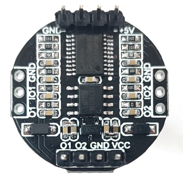
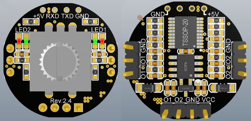
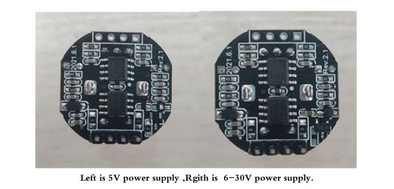
The red mark in the above picture is the spare function, which is not welded by default. The left and right LEDs are welded by default as LED2 red light, LED1 green light. O1 and O2 are analog output terminals, the maximum output voltage is 5V±2%, and the minimum voltage is less than or equal to 5mv. VCC is the power input terminal (with anti-reverse connection). The input voltage can be selected from 8-27V or 5V. If possible, it is recommended to use 8-27 power supply, because the on-board 5V voltage regulator circuit, the output is relatively stable. If you use 5V power supply, you need to ensure that 5V is stable enough. If the 5V voltage is unstable, the output will also be unstable.
The default number of steps is the same as the old version (1024 steps). If you need to change the number of steps, you can leave a message or contact the seller to modify it. The maximum number is 5000 steps. When the encoder rotates one grid, the output voltage change is the maximum output voltage divided by the total number of steps. One revolution by the encoder is 20 steps, for example, the total number of steps is 1000 steps, then 50 revolutions are required. Therefore, the fast adjustment function is added, and the output voltage changes faster when the encoder is rotated rapidly, thereby reducing the number of turns.
The default output voltage is two channels of 0-5V. If you need to change the output voltage range, such as 0-2.5V, you can contact the seller to modify it.
1.01 (0UT1), 02 (0UT2) output voltage 0-5V adjustable: the encoder rotates once, the output voltage change is 5/1024V: the encoder rotates one circle is 20 steps, 0-5V a total of 1024 steps.
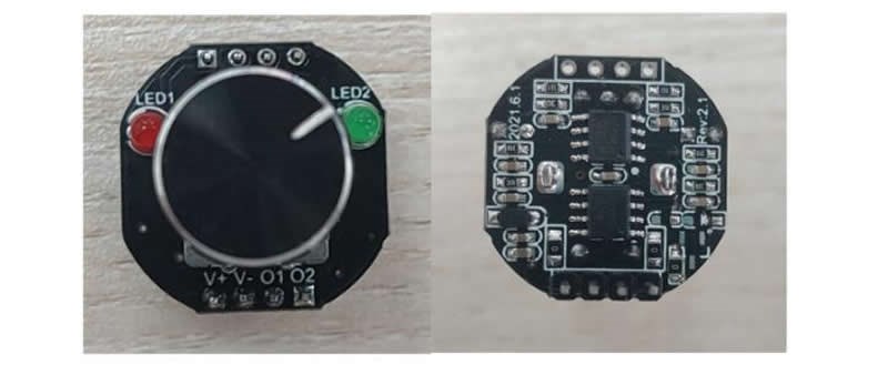
2. Power supply voltage 5V, 7-24V optional. V- (GND) is the negative pole of the power supply, and V+ (VCC) is the positive pole of the power supply.
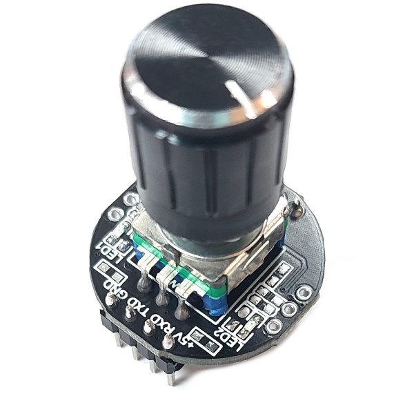
3. LED1, LED2 are output indicator lights, the red light is on to adjust the encoder to change the output voltage of OUT1, the green light is on to adjust the encoder to change the output voltage of OUT2, press the rotary encoder to switch the port to be adjusted is 0T1 or OUT2.
4. Increase clockwise: Rotate clockwise to increase the output voltage, and rotate counterclockwise to decrease the output voltage;
Increase counterclockwise: turn the output voltage counterclockwise to increase, turn clockwise to decrease the output voltage.
5. Memory:
No memory: The output voltage defaults to 0 when powered on: If the power is turned off, the output voltage will change to the default value of 0V
With memory: After adjusting, you need to press the encoder to save the current set value. After power off, the output voltage will keep the last set value unchanged. For example, now the green LED is on, turn the encoder to change the output voltage of OUT2, press the encoder to save after adjustment, and switch to another channel at the same time.
(The default sending is with memory, if you need no memory, you can leave a message after payment)
The 5V power supply model can also use 3.3V power supply, so that the output voltage becomes 0-3.3V, and the number of steps is still 1024;
The 6-30V power supply output voltage can also be changed to 0-3.3V, just replace the voltage regulator chip in the lower right corner with a 3.3V output;

The serial port control commands are as follows:
Send command data format is hexadecimal, baud rate 115200
The 0th and 1st bits 5A A5 are the frame headers, the 2nd and 3rd bits are the output voltage value of OUT1, and the 4th and 5th bits are the output voltage value of OUT2.
Corresponding relationship between sending command and output voltage: 00 00-04 00 corresponds to 0-5V
As shown in the figure above, the 2nd and 3rd bits are 00 00, and the 4th and 5th bits are 04 00. Click the send button. The output voltage of OUT1 is 0V, and the output voltage of OUT2 is the maximum value of 5V.

