Type:Logic ICs
Condition:New
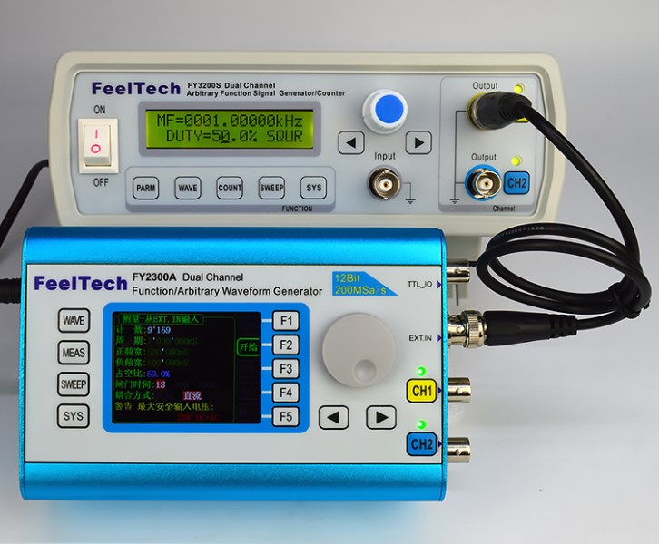
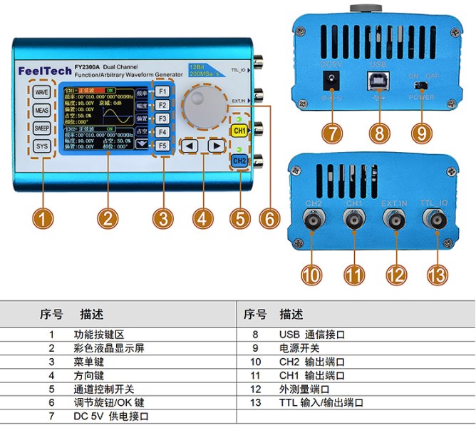
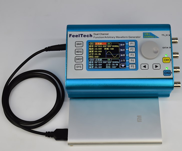
The main differences between the FY6300 and FY2300 series are as follows: 1. FY6300 series sine wave output frequency can reach up to 60MHz (FY6300-60M), square wave maximum output frequency can reach 25MHz, (the same performance parameter instrument price is above 2500 yuan), detailed parameter indicators can refer to different models corresponding Parameters Table. 2. The sampling rate of the FY6300 series is upgraded to 250MSa/s, and the high-frequency signal output contour is clearer; 3. The FY6300 series adopts 14-bit high-speed DA integrated circuit (DA scheme not built by other manufacturers' resistor network). When the output is 5V, the waveform step is as low as 0.3mV, and the waveform of the same price is the highest. 4. The waveform storage depth of each group of FY6300 series is upgraded to 8192*14bits, which can restore the signal details with high precision. 5, FY6300 series phase resolution can reach 0.01 degrees, the user can more precisely control the delay of the two signals; 6, FY6300 series duty cycle adjustment accuracy of up to 0.01%; 7, FY6300 series uses a new power supply design, eradicating the drawbacks of handheld instrument power supply noise interference with small amplitude signals. (10mV small signal still has perfect signal characteristics) FY2300 series dual channel function/arbitrary waveform generator is a portable, high performance and cost effective function integrating function signal generator, arbitrary waveform generator, pulse signal generator, frequency sweeper, counter and frequency meter. A versatile signal generator. The instrument uses a large-scale FPGA integrated circuit and a high-speed MCU microprocessor. The internal circuit uses a high-precision active crystal oscillator as a reference, and the signal stability is high. The surface mount technology greatly improves the anti-interference and service life of the instrument. The instrument has a completely independent dual DDS signal and TTL level output, which not only presets 31 common waveform signals for the user but also provides users with 16 custom waveform storage spaces. The instrument achieves the perfect combination of ease of use, excellent technical indicators and numerous functional features in signal generation, waveform scanning, parameter measurement and use, which can help users complete their tasks faster. It is an electronic engineer, an electronic laboratory, Ideal testing and measuring equipment for production lines and teaching and research. The FY2300 series dual channel function/arbitrary waveform generator has a user-friendly keyboard layout and indication, providing users with an intuitive operation interface. The display interface adopts a 2.4-inch TFT color LCD screen with 320*240 high resolution, which can display all the parameters of the two channels at the same time and prompt the current button functions. The shortcut keys greatly simplify the complicated operation process and greatly enhance the instrument. The operability. Users do not have to spend a lot of time learning and familiar with the operation of the instrument, you can use it.
Display interface comparison Multi-functional interface of our products: Each function has a separate interface, the display content is more abundant, the user operation is more intuitive, and the key reuse is greatly reduced. (For example: scan function interface. The information such as scan object, scan start frequency, scan time, scan mode, etc. can be displayed at the same time in one interface, and the user can intuitively operate and observe the current scan work status)
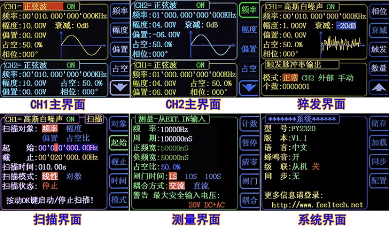
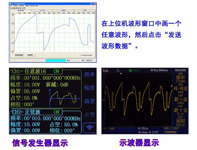
The interface of a peer: there is only one display interface from beginning to end, only one line in the middle of the screen to indicate the information of part of the user operation. And the user needs to frequently switch through the keys to observe the parameter information that I want to obtain. For example, the scanning function and the measurement function cannot be operated intuitively by the user. The set parameters cannot be visually seen by the user, and the set parameters are completely memorized by the user's brain. 3, waveform reproduction function Our effect: the industry's original waveform reproduction function, all waveforms output by the instrument can be displayed on the signal generator, including not only 31 kinds of preset waveforms, but also user-defined waveforms, which can be separated from the oscilloscope to some extent. For example: draw a waveform to the instrument output through the waveform drawing window of the FY2300 host computer.
Everyone knows the most important parameters of the signal: waveform, frequency, amplitude, and offset. These are the most basic and are closely related to the hardware. 1. About the bias level: In many debugging circuits, the bias signal needs to be adjusted arbitrarily. For example, the debug comparator circuit needs to superimpose a DC component on a small signal, and the value of this DC component is Arbitrary (for example, the signal peak is 0.5V, and a DC component of 2V needs to be superimposed). Our bias: can be adjusted from -10V to +10V. As shown below:
Let's take a look at the DC offset of a certain business. In any case, it can only achieve 0.5 times the peak-to-peak value of the output signal. That is to say, the signal outputting the peak-to-peak value of 0.5V can only be superimposed with a 0.25V DC offset. Go to a reference 2.5V comparator circuit. And careful friends can find that even if this is the case, his bias is due to the defect of the hardware design. When the signal amplitude changes, the offset will be unreasonable, so the "high man" will do it in the whole range. A few stages of software compensation, so you appear from small to large amplitude, his bias will dance up and down. 2. About small signals: our 10mV and 5mV small signals
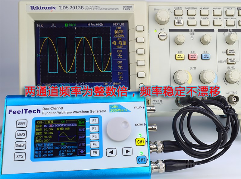
3, on the frequency accuracy: may not be able to get a standard value due to factors such as test equipment and ambient temperature, but you can use a dual trace oscilloscope to test the two outputs of the same source, when the two signals are output When the frequency is an integer multiple (for example, channel 1 output 20KHz, channel 2 output 40KHz), at this time, the starting phase of one of the two waveforms should be strictly consistent. If one waveform is stable on the oscilloscope, the other waveform is around. Floating, that means that the two waveforms must not be an integer multiple, then it is absolutely inaccurate to prove that at least one of the two signals is a frequency. This is what a trader calls "high-precision signal source". You can test our The signal source, as a frequency reference source, our two frequencies are stable.
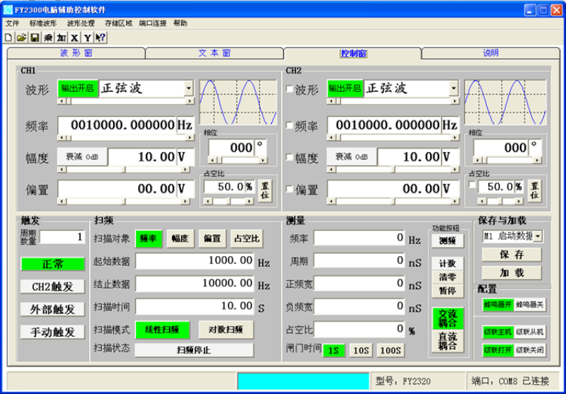
◆ With our FYV2000 series or FPA1000 series power amplifier, the signal can stably output a distortion-free power signal greater than 20W in the DC-3MHz bandwidth, and the FPA1016 output power can be up to 60W. ◆Multi-function PC software: standard arbitrary waveform editing function, can edit arbitrary waveforms on the PC to download to the instrument and output waveforms; all the function parameters of the instrument support the software control of the host computer, the communication protocol is open, so that you can develop twice Very simple; PC software interface is as follows:
◆Multi-function handheld and other advantages: Only need a mobile power supply to work outdoors for a long time, and realize the function of the desktop signal source with the smallest body.
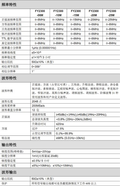
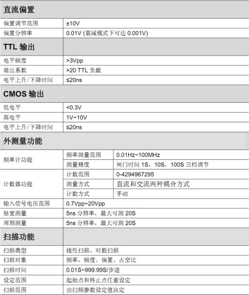
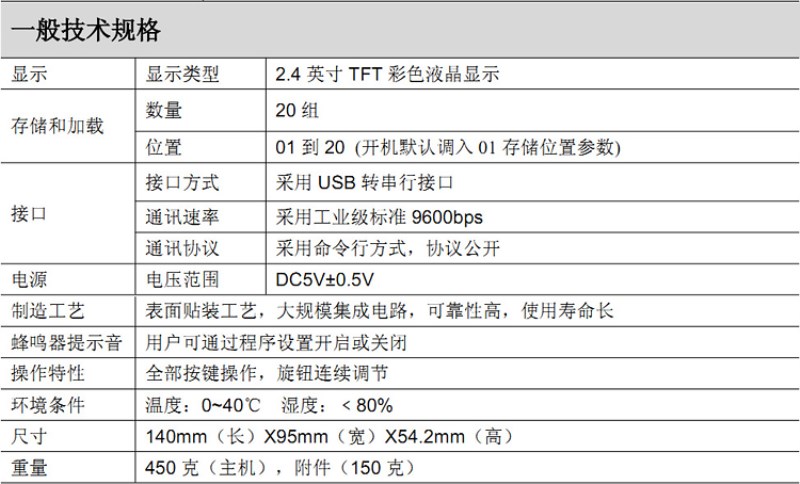
Technical indicators
Performance Testing
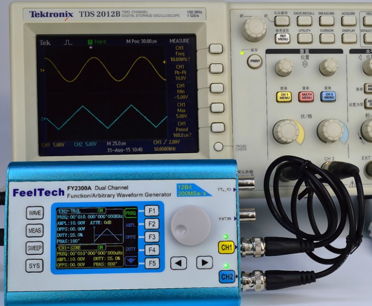
1. The CH1 channel outputs 10KHz sine wave, and the CH2 channel outputs 10KHz triangle wave. The output of the instrument is exactly the same as the frequency measured by the oscilloscope. This is actually an accurate online calibration, which can make the frequency output not worse.
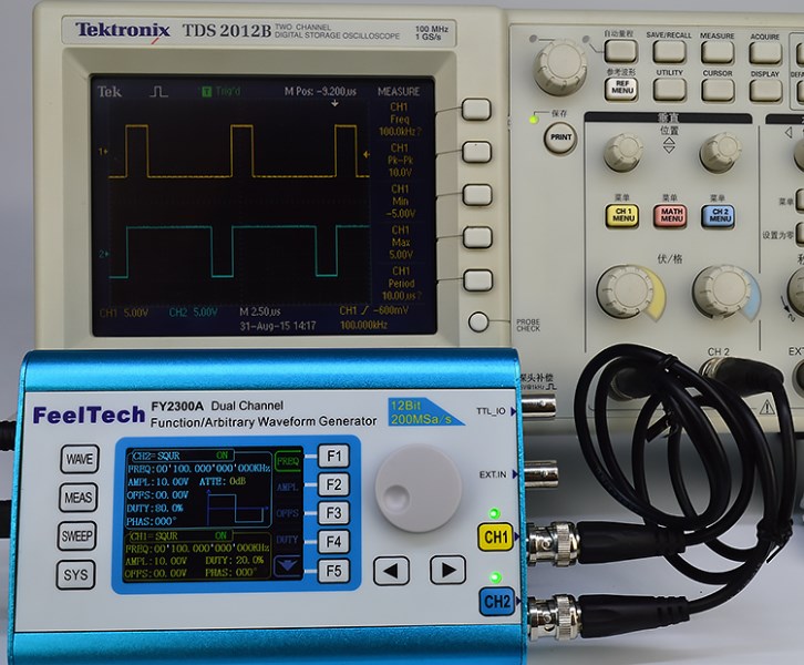
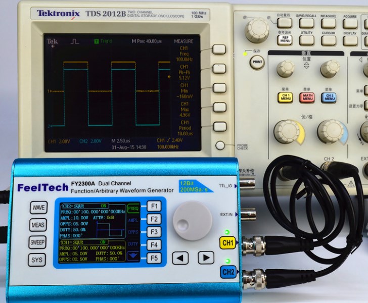
2. CH1 channel output frequency is 100KHz, duty cycle is 20% square wave; CH2 channel output 100KHz, duty cycle is 80% square wave; square wave mode, duty cycle can be set arbitrarily, resulting in duty Compared with the adjustable pulse wave, the adjustment accuracy is accurate to 0.1%.
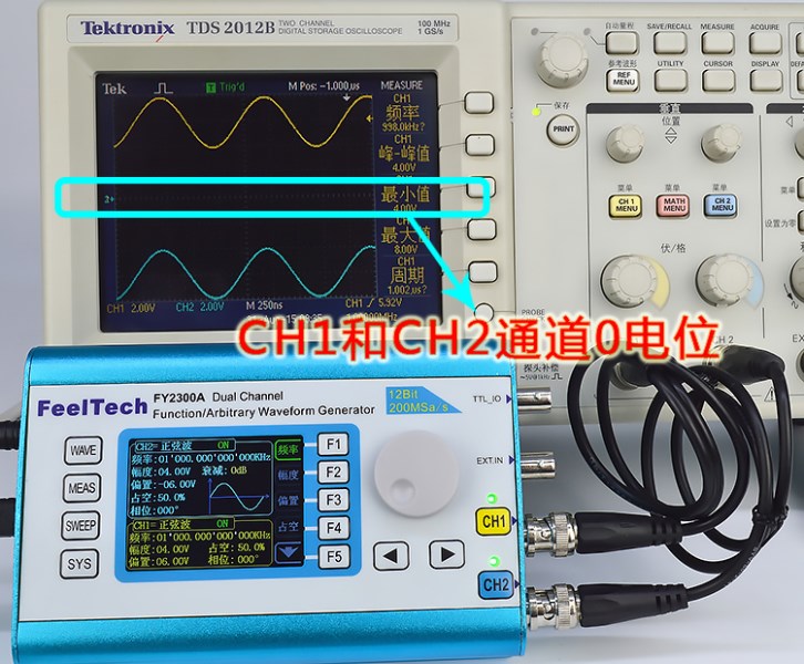
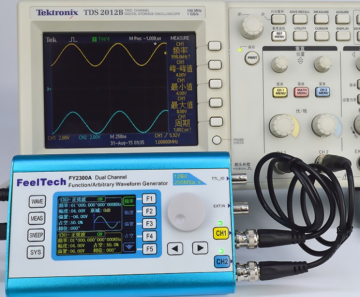
3, CH1 channel output 1MHz amplitude 4V, biased 6V sine wave; CH2 channel output 1MHz amplitude 4V, biased -6V sine wave; (output signal bias level can be -10V to +10V Arbitrary adjustment)
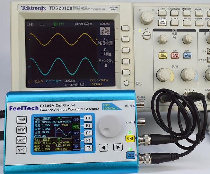
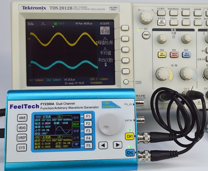
4, CH1 channel output amplitude is 100mV small signal, CH2 channel output amplitude is 50mV small signal
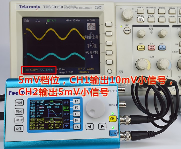
5, CH1 channel output amplitude is 10mV small signal, CH2 channel output amplitude is 5mV small signal
6. In the square wave output state, adjust the bias level to enable the instrument to output digital signals, and the amplitude of this digital signal can also be adjusted, so the instrument can output 1.2V, 1.5V, 1.8V, 3.3V, 5V, 10V equal amplitude is 0~10V arbitrary CMOS level. As shown in the figure below: CH1 channel output amplitude is 5V COMS level, CH2 channel output amplitude is 10V COMS level.
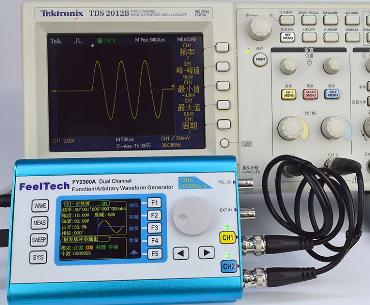
7. Burst burst output function: optional manual trigger, internal CH2 trigger and external trigger three trigger modes, which can make the machine output 1~1048575 arbitrary pulse trains; pulse train type, pulse number, trigger mode users can
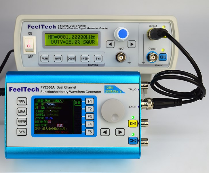
8. Frequency meter function: It has five kinds of measurement methods: frequency measurement, period measurement, positive pulse width measurement, negative pulse width measurement, and duty cycle measurement, and five kinds of measurement methods can be simultaneously performed and displayed in real time. Gate time 1S, 10S, 100S three gears are optional. The maximum measurement frequency of the instrument can reach 100MHz, and the lowest measurement frequency is 0.01Hz; Application examples: (1) Measure the frequency of the FY3200S series signal source output is 1KHz, the square wave signal with the duty ratio is 25%, and the gate time is 1S. The measurement result is as shown below: The measured frequency is displayed as 1000Hz (100S is selected for the gate time, and the measurement result can be accurate to 0.01Hz) The measurement signal period is displayed as 1000000ns (the frequency and period of our instrument are two different measurement methods. The minimum frequency can be measured to 0.01Hz, and the maximum period is measured to 20S) Measuring the positive pulse time with a duty cycle of 25% square wave, the measurement result is 250,000 ns Measuring the negative pulse time with a duty cycle of 25% square wave, the measurement result is 750,000 ns Measuring the duty cycle of the square wave, the result is 25.0%
9. Counter function: It has two kinds of coupling measurement methods, DC and AC, which effectively solve the problem of inaccurate AC coupling count. You can press the start button to count, the pause button to pause the count, and the clear button to clear the count. In the counting state, the instrument can also measure the period, pulse width and duty cycle of the signal simultaneously. As shown below: