Condition:New
Type:Logic ICs
Upgraded version: The voltage amplification and phase inversion are changed to the Soviet tube 6H3n 6H1n, and the coupling capacitor is changed to the US imported Sibi.
This is an improved traditional model.
Performance introduction
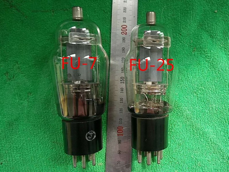
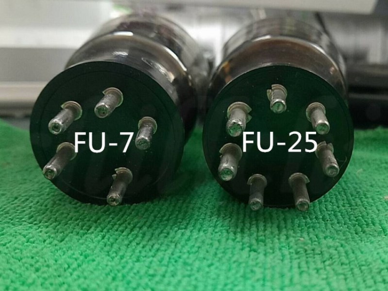
FU-7 (foreign model 807) push-pull power amplifier has a long history and a huge social possession. Have you ever remembered that most of the loudspeakers we heard in rural factories and mines used it for most of the amplifiers. After several generations of research and improvement, coupled with modern high-tech, its sound quality is no longer what it used to be. From the point of view of electrical parameters alone, it is not as good as KT88 KT100 300B, 845 211, and even less than 833 7092. But the melodious and sweet midrange, deep bass, and crisp treble of 807 are unparalleled. They accompany us to school, read, and work all the way, unforgettable. The airy feeling of 807 is rare in other pipes, and it is breathtaking and endless aftertaste. The tube similar to FU-7 has the FU-25 (foreign model 1625) pin, the filament voltage is 12.6V, other parameters are exactly the same, the sound quality is exactly the same, but its price is lower, only about half of 7. Fans who lack silver can choose it.
The current model is meticulously designed and produced by me through more than 30 years of research and experimentation, and gathered feedback from fans. The starting point of the design is to face the working people, carefully select materials, and make the sound as cheap as possible.
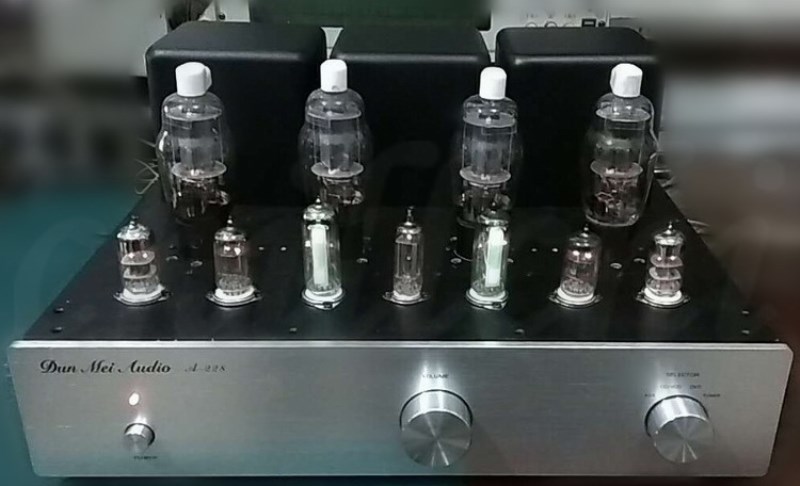
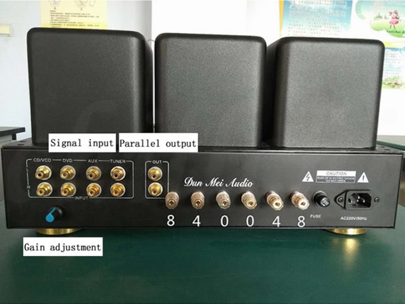
The output power is 2*50W, the weight of the whole machine is about 20KG, the chassis is made of 1.0 iron plate, the upper bottom plate is 2.0 sandblasted black aluminum plate, the front panel is 43.5CM wide, 9CM high, and 0.6CM thick aluminum plate, and the cow cover is 1.0 Black sandblasted iron plate is stamped and formed. The shape is 23CM high, 42.5CM wide and 38.5CM deep. Shared 11 electronic tubes, 4 FU-7, 2 6N3, 2 6N1, 2 6E2, and 1 6Z4. High voltage 630V, medium voltage 300V, negative voltage 60V. Output impedance P-0-P 5K-0-5K. 4 inputs, output 0-4-8 ohms.
Production process
This article explains the design and production process of this machine in more detail. Fans with a little electronic foundation and hands-on ability can imitate a high-quality, cheap and beautiful-sounding tube amplifier.
One. Circuit principle design: At present, there are many electron tubes used in the front stage, and the commonly used ones are 12AU7, 12AT7, 6N8P, 6J8P, etc. Here we choose the cost-effective peanut tube, and the voltage amplifier uses the medium-L high-frequency tube 6N3, which is a high-frequency voltage amplifier. Double triode, medium L (L=35) value, low screen voltage, suitable for small signal amplification, this tube was often used in TV tuner before, with good performance, it is a music-type voltage amplifier tube, and The sound is sweet, mellow, clear and transparent, and the low frequency is strong enough. Because it is a high-frequency voltage amplifier tube, the high-frequency performance is also particularly delicate and transparent. As there are not many people hyping up, the price of this bile is low, and it is an excellent bile duct with great value. Connect it as a cathode output, the distortion is smaller and the driving force is better. Inverted phase amplification uses double three-level L (L=35) 6N1. This tube has a relatively average tone, a strong musical taste, a good linearity, and a full and soft mid-frequency performance, especially for the bile ducts with excellent vocal performance. Traditional inverter circuits all use transformers for phase inversion. The characteristics are that the push-pull arms are easy to be symmetrical, the circuit is simple, easy to adjust, high gain and high power can be achieved, the midrange performance is good, and both ends are inferior. We use a long tail phase inverter circuit, which is characterized by balanced tone and low distortion. If the push-pull arms are adjusted to a complete balance, not only the midrange is good, but the high and low ends perform very well. Compared with using a transformer for phase inversion, the cost can be much reduced. The front stage and the phase-inverted drive circuit adopt direct coupling, which is also the key to the beautiful sound of this machine and reduces the cost. Generally, the circuit adopts capacitive coupling. No matter how good capacitors you use, distortion will occur. The disadvantage of direct coupling is that all levels of amplifiers are connected to each other, making it difficult to debug. The power amplifier stage adopts fixed bias voltage, high power and good dynamics. The static operating points of the two push-pull power amplifier tubes can be completely adjusted to the same to ensure the sound quality. The disadvantage is that a negative voltage needs to be added. The output impedance of the traditional machine 807 is mostly 6.9K. This value guarantees a large gain and a large output power. The midrange sound is good, but the bass is slightly worse. This does not meet our high-fidelity concept. When the impedance is increased to 10K, the distortion is greatly reduced, and the gain and power can also meet the requirements. Negative feedback can effectively reduce distortion, but it also loses the vitality of music and reduces dynamics and layering. This is a contradiction. For this reason, we set the negative feedback to be adjustable to meet different ears.
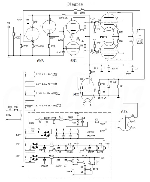
The power supply is the key to a good power amplifier. The filament voltage must have a small error and sufficient current. The high-voltage 630V adopts transistor rectification and relay delay to protect the power amplifier tube. The delay circuit is composed of two transistors, and the delay time can be changed by 270K resistance or 100UF capacitor. Traditional models often use bile rectification. Some people say that bile rectification is good. I think it is a mistake. Rectification is to convert AC to DC. The unidirectional conductivity of diodes is used. The difference between them is that the internal resistance of bile rectification is larger. , Crystal diode = electronic diode + resistance, single-ended class A machine needs relatively pure and stable current, it is more suitable to use bile rectification, while push-pull machine needs a power supply that can provide enough instant current, compare with internal resistance Small transistors are more suitable for rectification. In the past, there were no large-capacity and high-voltage capacitors, which was also the reason for the use of bile rectification. The medium-voltage 300V voltage is taken from a separate winding of the transformer and can also be powered by a high-voltage intermediate tap. The transistor rectifier is buffered by 6Z4, or a simple voltage regulator circuit is used to protect the front stage electron tube. This voltage must be pure and stable.
two. Component selection and layout: The capacity of the case must be large enough. If the height of the case is greater than 10CM, the power transformer can be placed in the case. The 6N1 push tube should be placed between the two power amplifier tubes, and the 6N3 is next to it. Use twisted-pair wires for filament wiring, as far away as possible from other circuits. The direction of the signal channel cannot be parallel to the power supply, and the input end is far away from the power transformer.

Metal film resistors are used as resistors, and different power sizes are selected according to different uses. The gate resistors are 1W or less. Don't think that the larger the resistance, the better, just meet the power needs, and the principle is not to generate heat. The resistance is large, and the contact surface with the outside is also large, and it is easy to sense external clutter and generate unwanted noise. Coupling capacitors are best to use oil-immersed capacitors, or Weimaxi, etc., and the most common and cheap CBB film capacitors are also acceptable. Don't think it is cheap. In fact, it is very good and cost-effective. The power supply filter capacitor uses 220V450V electrolytic capacitor commonly used in ordinary TV sets. One more thing, for this machine, there is no need to use tens or hundreds of yuan of capacitors. If you don't believe it, you can use it instead, the sound quality does not affect much.
Don't choose too expensive electron tubes, just tens of yuan ordinary tubes. The exception is local tyrants.
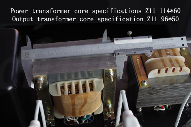
The second-hand Z11 iron core used in the transformer may have poor appearance, but not inferior in performance. The power transformer uses 114 pieces, the stack thickness is 60MM, and the power is greater than 370W. If the chassis is large enough, a large iron core should be used as the power supply, which can reduce the internal resistance of the power supply and is good for low frequencies. The power supply filter capacitor capacity should be sufficient, and the voltage drop should not be large when the power is full to ensure full and thick bass. Elementary, 220V: 0.83 line 375 turns, with 0.08 telephone paper between layers and painted. Secondary, 460V: 0.51 wire 810 turns, 405 taps, 0.05 telephone paper between layers and paint. 60V: 0.25 wire with 100 turns. 12V: 0.38 line with 22 turns. 6.3V: 1.04 wire, 11 turns, 4 groups, one of which has a center tap. Use yellow wax to thicken +0.08 telephone paper between layers and paint. The insulation between primary and secondary must be handled well, yellow wax thick + 0.08 paper 2 layers + copper foil + yellow wax thick + 0.08 paper 2 layers. There are no technical requirements for power transformers, one word: tight. Don't use an automatic wire winding machine, use that simple winding machine to wind the wire manually. Two output transformers, with 96 pieces, stacked with a thickness of 50mm. Use king frame, 4 primary groups, 0.25 line 4*850 turns. Secondary 3 groups, 1.16 lines 34+32+32=98 turns. Don't use too thick wire for the primary stage. 0.25 is enough. When the current density is 2.5, the average current is 120MA, which fully meets the needs of the power amplifier tube. Using thick wires can reduce wire resistance, but the number of turns and inductance should be reduced accordingly. When making, open a gap in the middle baffle of the king character frame, and firstly wrap it with 1.16 wire for one layer, which can be wound around 34 turns. The insulation between the groups is thickened with yellow wax + 0.08 telephone paper and painted. Then use 0.25 wire to close 850 turns in one of the interlayers of the frame, as flat as possible, without insulation between the layers, without painting (Question: Is this insulation enough? Is it safe? According to experience, use high-quality enameled wire and carefully wind it. , Dont scratch the line, no problem. No paint, close winding is to reduce the distributed capacitance, because the dielectric constant of air is much smaller than that of insulating paint, and the sense of hearing is much worse). Finish this group. Remove the frame from the winding machine, turn it over, and wind another 850 turns, adding insulation between groups. Then use 1.16 wire to wind 32 turns. Note that because the previous winding cannot be absolutely flat, this winding cannot be wound with 34 turns. Then wind two 850s forward and reverse, and then 32 turns of 1.16. Finally, 98 turns of around 0.3 wire are used as the feedback winding. The iron core clamp is processed into 16*80MM with 2-3MM glass fiber board, with 5.5 holes at both ends, and clamped with M5*100 screws. No iron clamp is used to reduce the eddy current of the transformer. Reminder: The output transformer is very important!
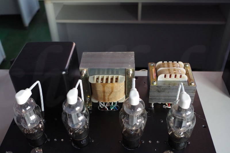
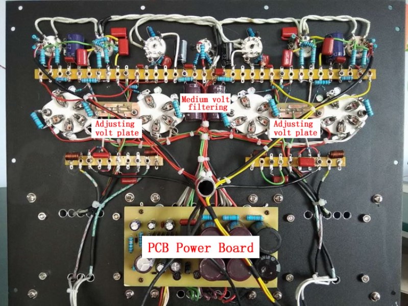
three. Installation and commissioning: sit down to make the machine,Calm down, treat the machine as a work of art, polish it carefully, and don't be anxious when encountering problems.All the components on the circuit are installed on the upper base plate, the power transformer and the output transformer should have a proper distance, and the magnetic lines of the two should be installed perpendicular to each other. For the convenience of installation, the power supply part can be installed on the PCB circuit board, of course, it can also be welded on a scaffold. For the convenience of adjusting the quiescent current of the power amplifier tube in the future, a small hole can be made next to the corresponding power amplifier tube to leak the negative pressure adjustment potentiometer. Make a wiring board and install it between the power amplifier tube and the front tube to install fixed components. The bias resistance and capacitance of each tube may be short as soon as possible, and it is best to install it on the pin to minimize interference. The necessary wiring should be far away from the filament and transformer wiring. All ground wires adopt the principle of nearby grounding, but the signal ground and power ground must be separated and cannot be parallel or overlapped. The signal shielding layer cannot have the slightest current flow.
The more troublesome thing about this machine is the static adjustment of the front stage, which is adjusted step by step from front to back. First adjust the first half of 6N3, change the resistance of the cathode machine and the load resistance of the anode, so that the static current is about 4MA, and the anode voltage is about 150V. , Then adjust the other half of 6N3, change that cathodic resistance, make the quiescent current about 5MA. Most long-tail inverter circuits have two gate resistances of 1M, which I think is inappropriate, because 6N1 has a small gate current, and there is a voltage drop across that resistance. The larger the resistance, the higher the voltage drop, which makes the push-pull The two arms are severely uneven. For this reason, the grid resistance is reduced to between 100K-200K, and a resistor of several K is added between the two cathodes and adjusted to make the currents of the two arms exactly the same. The quiescent current of 6N1 is about 5MA. Note that the quiescent current of each tube should not be too small, and it must work in the linear region, which has a great impact on the sound quality. But the current should not be too large, which will affect power consumption and life. Finally, connect the high voltage and adjust the negative pressure to make the quiescent current of each power amplifier tube consistent. The current size is up to you.

Signal input-signal selection switch-potentiometer--6N3 grid, the connection should use shielded wire.
Through the meticulous production day and night, you will be delighted when it is finished, booted, and listened to. It doesn't cost much, but it can be compared with any brand-name machine.
------------------------------------------------------------------------------------------------------------------------------------------------------------------------------
The DIY description:
Wiring diagram (high-definition large image is available for free)
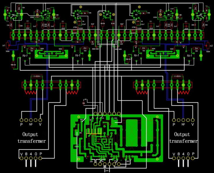
Tip: Be careful of high voltage during debugging
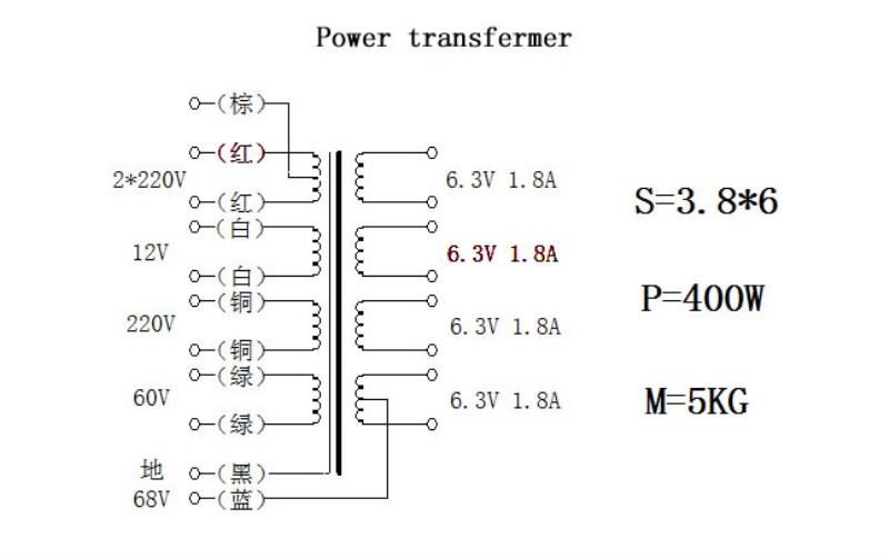
1.Power transformer:ChooseZ11Iron core, relatively high permeability,S=3.8*6,which is114Slices, stacked thick6CM, Core power500Wabout. Transformer power400Wabout. primary220V, Wire diameter selection0.85-0.9High-strength enameled wire (a little thinner for beginners,Lest the window is too small), bypass373Turns, used between layers0.08Phone paper. Secondary,1.High pressure can be440V-460VBetween (corresponding to DC voltage600V-630VBetween) High voltage and high power. Wire diameter selection0.44-0.51Wire760-800Turn, tap in the middle, do medium voltage. Between layers0.05Phone paper.2.Negative voltage winding current is very small, there is no requirement for wire diameter, just a little thinner, generally used0.twenty one-0.25Wire around100Turn around. Voltage60Vabout.3. 12VFor winding0.3Left and right winding21Turns.4.Filament shared4group6.3V1.8A, The two left and right channelsFU-7Use one winding for each,6Z4And two6E2Use one winding, two6N1,6N3Use one winding, this one must have a center tap. The long-term working current of the filament voltage is larger, and the current density is smaller.0.95-1.00Wire wound11Turn. There must be a shielding layer between the primary and secondary, and lead to ground with a wire. Between groups2Floor0.08Phone paper plus1Floor0.08Thick yellow wax. Brush insulating paint between layers. The effect of painting between layers is much better than dipping the entire transformer. Don't believe in vacuum dipping, it is difficult to soak inside the transformer. Power transformer coil weight1KGAround, the transformer is heavy5KGabout.
2. Output transformer: optionalZ11High quality iron core,96Slices, stacked thick5-6CM. Output impedance8-10K,Primary use0.25, Secondary use1.14.Use the king character skeleton,3+4Around. There is no insulation between layers and no varnishing. Between groups2Floor0.08Phone paper+0.08Thick yellow wax.
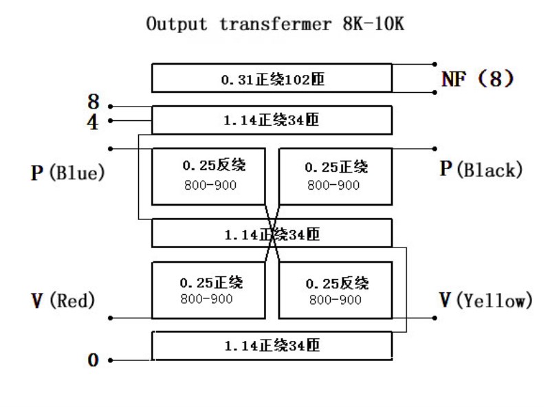
The output transformer is two sets of independent windings.V(Red) andV(Yellow) connect to high voltage,P(Blue) andP(Black) Connect separatelyFU-7The screen (high pressure cap). Pay attention to the phase of the feedback winding. If it is connected reversely, it will be severely self-excited.
three. Selection of resistance and capacitance: all the internal resistance of the machine uses metal film resistance, which has good performance and small error. For gate resistor0.5WOr smaller, the wiring should be short. The principle of using other resistors is that the heat is not large, and it can ensure long-term safe work. by6N1Coupled toFU-7The capacitor has an impact on the sound quality, you can use oil-immersed capacitors, here is Sibi0.47Audio capacitor. Withstand voltage of front capacitor400V.
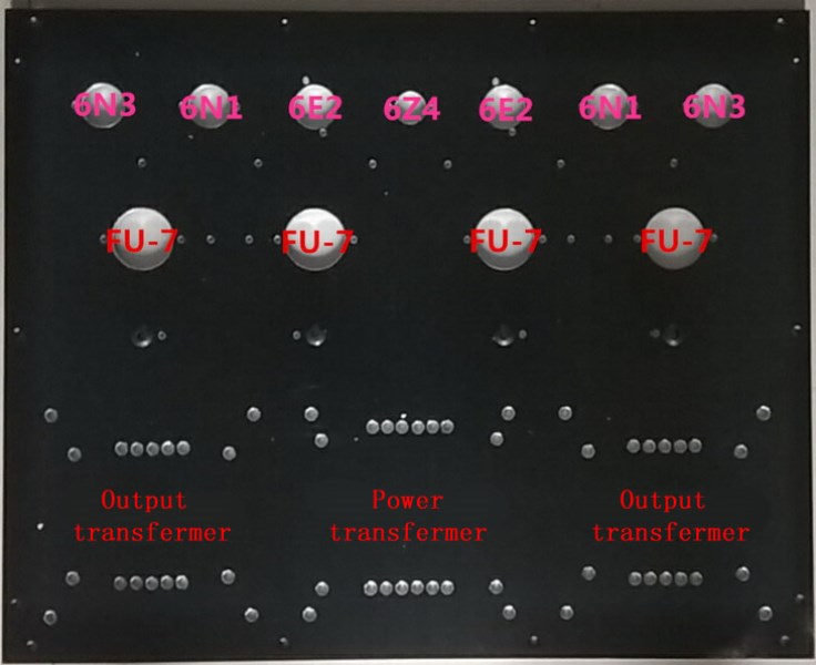
Punched bottom plate
FU-7Push-pull tube amplifier ingredients list
|
name
|
specification
|
Quantity
|
Instructions for use
|
Case
|
|
1
|
Knobs, feet, power sockets, fuse holders. The upper and rear plates have been punched
|
Terminal
|
Red 4 black 2
|
6
|
|
Lotus terminal
|
Red 5 black 5
|
10
|
|
Double potentiometer
|
500K
|
2
|
Use one for volume and feedback
|
Band switch
|
2*4
|
1
|
Input signal selection
|
Power PCB board
|
Debugged
|
|
Output voltage: 630V, 60V, 12V, 300V
|
FU-7 tube socket
|
|
4
|
5 feet: 15 filament 2 medium voltage 3 grid 4 cathode
|
Small nine-pin tube socket
|
|
6
|
Pay attention to the same direction of the filament of the tube when installing
|
Small seven foot tube socket
|
|
1
|
For 6Z4
|
Negative pressure regulator board
|
|
2
|
Installed between two FU-7
|
Wiring board
|
|
3
|
Separate with nylon column and base plate during installation
|
Double terminal
|
|
|
Use screws for grounding
|
Screw nut
|
|
|
|
Electron tube
|
|
7
|
6H1n two 6H3n two 6E2 two 6Z4 one
|
Resistance and capacitance
|
|
|
Resistor Capacitance LED Diode
|
Coil
|
self made
|
|
Use about 1.0 enameled wire to wind 10 turns on a 5-6MM coarse drill bit
|
High pressure cap
|
|
4
|
|
Wire
|
|
|
section
|
|
Resistance and capacitance components used in this machine
Numbering
|
specification
|
Description
|
|
Numbering
|
specification
|
Description
|
R1
|
470K/0.5W
|
|
|
R2
|
33K/2W
|
30K-36K
|
R3
|
560/1W
|
560-680
|
|
R4
|
33K/2W
|
30K-36K
|
R5
|
200K/0.5W
|
|
|
R6
|
2K/1W
|
1K-2K
|
R7
|
18K/2W
|
18K-20K
|
|
R8
|
27K/2W
|
24K-27K
|
R9
|
27K/2W
|
24K-27K
|
|
R10
|
1K/0.5W
|
|
R11
|
1K/0.5W
|
|
|
R12
|
100K/0.5W
|
|
R13
|
100K/0.5W
|
|
|
R14
|
100/2W
|
|
R15
|
100/2W
|
|
|
R16
|
30K/0.5W
|
30K-47K
|
R17
|
91K/1W
|
|
|
R18
|
270K/0.5W
|
|
R19
|
1M/0.5W
|
|
|
R20
|
1K/1W
|
|
R21
|
100/2W
|
|
|
|
|
|
C1
|
22UF
|
|
|
C2
|
0.1
|
|
C3
|
0.47
|
|
|
C4
|
0.47
|
Quality coupling
|
C5
|
0.47
|
Quality coupling
|
|
C6
|
0.1
|
|
C7
|
|
|
|
C8
|
0.1
|
|
C9
|
100UF
|
|
|
C10
|
0.047
|
|
C11
|
0.022
|
|
|
Q1: What Is Your Product Warranty?
A: We Guarantee Our Product Is Fit For Its Normal User Purposes And Is Free From Defects In Materials Or Workmanship.
Q2: What Is Your Company Policy On Defective Goods?
A: Our Company Keep Items Quality For A Long Time. If There Are Any Defective Goods Due To
Production Defects Or Transportation Problem, Please Contact Us. Our Customer Service Team Will Provide Immediate Response To
Complaints. We Will Try Our Best To Give You A Good Resolve Way.
Q3: What Is Your MOQ (minimum Order Quantity)?
A: Generally Our Moq Is No Limited. Please Have More Discussion With Us If Your Combination Of Models Is Complicated.
Q4:how About Getting Samples From You?
A: We Will Send You The Samples After We Receive The Payment For Samples. The Buyer Shall Afford The Shipping Cost. Please Have A
Confirm With Us Which Shipping Way Do You Want.
Q5:about The Shipment: What Type Of Shipment Will You Use?
A: We Usually Ship The Products By Express(delivery It To Your Door) Or By Air Freight To Your Nearest Airport, Shipping Days:3-7
Working Days Depend On Destination;if The Order Quantity Is Large, We May Ship By Sea Container And The Best Ship Way Is By Sea,
Shipping Days: Over 20 Working Days Depend On Destination Port.
Q6:what Packing Do You Use?
A: Neutral Package With Airbag Or Customized Package.
Q7:how Much Are The Shipping Cost?
A:shipping Cost Is Charged By The Package's Weight And Related To The Shipping Methods You Choose And Your Destination.
Q8:how To Order?
Step1.Click (Add to Cart) Buy Directly On The Product Page, Or Add To Shopping Cart And Settle Together, Pay With Paypal,
Need your information, such as full name,country, city, detail address, post code, tax number ...
Step2. We Will Delivery by EMS POST, FedEx or DHL Within
3-5 Working Days After Payment Confirmed.
Setp3. Confirm Us Receipt of Products.
|