Condition:New
Type:Logic ICs
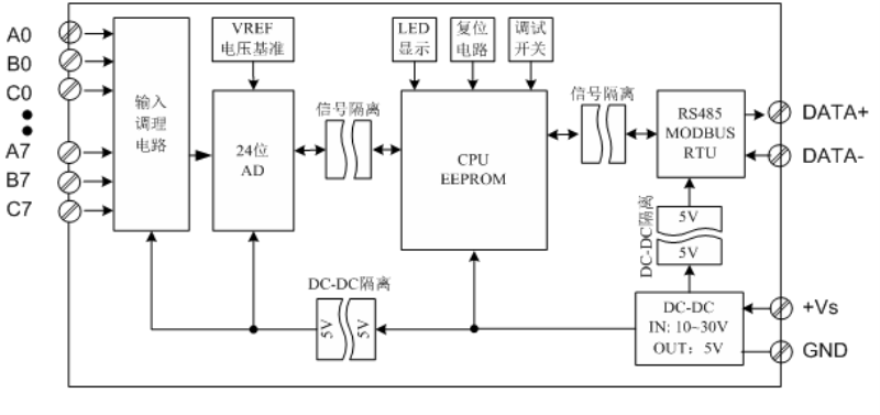
MB8ART8High-precision mixed-signal acquisition module, which can acquire analog quantity (±20mA,4-20mA,±15mV,±100mV,±1V),8Thermocouple(J/K/T/E/R/S/B/N),2Kind of platinum resistance (PT100,PT1000,CU50,CU100) And many other signals, and the signal type of each input channel can be combined at will. The collected analog signal data, through isolationRS485Interface output; module adoptsModbus-RTUCommunication, adaptable toPLC,DCSAnd various configuration software, etc.
Signal input, CPU, power input and RS485 communication electrical signals are isolated from each other, effectively suppressing various serial mode and common mode interference, ensuring data accuracy, and also ensuring the reliable operation of the module.
MB8ARTThe module is mainly used in applications where temperature acquisition and multiple analog input signal types coexist. It can be widely used in iron and steel smelting, metal heat treatment, chemical industry, metallurgy, glass processing, injection molding temperature control, tobacco, medicine, automatic complete sets of equipment, and so on.
- Features
8Mixed signal input (thermocouple, platinum resistance thermometer and analog quantity),The input signal type of the channel can be set according to your own needs.
Thermocouple, thermal resistance and 4-20mA input have the function of detecting disconnection, which is convenient for on-site debugging and maintenance.
Fully differential input, and each channel is isolated from each other.
High-precision signal acquisition: High-precision twenty four-bit AD and voltage reference are used, and the temperature coefficient of the voltage reference is 10PPM/°C.
Independent high-precision cold junction compensation, accuracy ±0.5°C.
Safety: Signal acquisition, signal output, power supply, and RS485 communication electrical signals are isolated from each other.
The standard Modbus-RTU protocol is adopted, and the RS485 communication signal output interface adopts double protection of overvoltage and overcurrent.
The input signal type and communication format can be set by software.
Power input polarity protection and overvoltage protection.
Technical index
project | parameter |
AI signal input | 1.Input channel: 8 differential inputs,Mutual isolation between channels 2.Isolation voltage between channels: 300V 3.Input signal type: 8Types of thermocouples (J, K, T, E, R, S, B, N) 4SpeciesTypes ofThermal resistance(PT100,PT1000,CU50,CU100) 2TypeCurrent input (±20mA,4~20mA) 3TypeVoltage input (±15mV,±100mV,±1V) 4.Setting method: through software setting, the current input also needs to short-circuit the jumper on the circuit board 5.Scan period: 8 channels are collected every 500mS. 6.ADResolution: 24 bits. 7.Signal acquisition circuit and power input isolation voltage protection: 1000V |
RS485 Communication output | 1.Communication protocol: standard MODBUS-RTU. 2.Communication distance: @9600bps 1200 meters. 3.Communication medium: ordinary twisted pair cable, greater than or equal to 0.5mm2. 4.Interface type: isolated RS485 communication, the output interface adopts double protection of overvoltage and overcurrent. 5.Baud rate: 1200bps, 2400bps, 4800bps, 9600bps, 19200bps, 38400bps 57600bps, 115200bps. 6.Parity: no parity, even parity, odd parity. 7.Data bits and stop bits: 8 data bits, 1 stop bit, these two parameters are not adjustable. 8.Power input and RS485 circuit isolation voltage protection: 1000V. 9.Setting method: module address, baud rate and parity can all be set by software. |
Module size | 1.Individual module size: L104mm * H72mm * H26mm 2.Box size with terminal and guide rail: L124mm * W72mm * H45mm |
Installation method | Standard 35mm DIN rail installation |
working environment | 1.Temperature: -10 +55°C 2.Humidity: 35 ~ 85% (no condensation) |
Power supply | 1. Power supply voltage: 10V ~ 30V wide range power supply, with power supply polarity protection 2. Power consumption: less than 2W |
measurement accuracy | Input type | Measuring range | display resolution | Precision |
Thermocouple | J(-2001200°C) | 0.1C | ±0.4°C |
K(-2001370) |
T(-200400) |
E(-200950) |
R(-201750) | ±0.6 |
S(-201750) |
B(6001800) |
N(-2501300) | ±0.4 |
Cold junction compensation | -2080 | 0.1 | <±1 |
Thermal resistance | PT100(-200850) | 0.1 | ±0.1FS |
PT100(-200850) | 0.1 | ±0.1FS |
CU50(-50150) | 0.1 | ±0.1FS |
CU100(-50150)) | 0.1 | ±0.1FS |
Current input | ±20mA and 420mA | 0.001mA | ±0.1FS |
Voltage input | ±15mV | 0.001mV | ±0.1FS |
±100mV | 0.01mV | ±0.1FS |
±1V | 0.0001V | ±0.1FS |
- Product appearance, terminal definition and status indication
Appearance
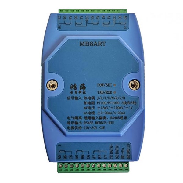
Terminal definition
Terminal | name | Description | | Terminal | name | Description |
1 | A5 | Input signal channel 5 positive terminal | 26 | C4 | Platinum resistance input C4 |
2 | B5 | Input signal channel 5 negative terminal | 25 | B4 | Input signal channel 4 negative terminal |
3 | C5 | Platinum resistance input C5 | 24 | A4 | Input signal channel 4 positive terminal |
4 | A6 | Input signal channel 6 positive terminal | twenty three | B3 | Input signal channel 3 negative terminal |
5 | B5 | Input signal channel 6 negative terminal | 22 | A3 | Input signal channel 3 positive terminal |
6 | C6 | Platinum resistance input C6 | 21 | C23 | Platinum resistance input C23 |
7 | A7 | Input signal channel 7 positive terminal | 20 | B2 | Input signal channel 2 negative terminal |
8 | B7 | Input signal channel 7 negative terminal | 19 | A2 | Input signal channel 2 positive terminal |
9 | C7 | Platinum resistance input C7 | 18 | B1 | Input signal channel 1 negative terminal |
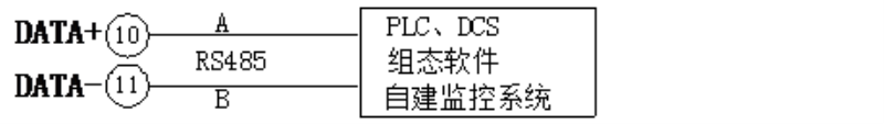
10 | DATA+ | RS485 ACommunication+ | 17 | A1 | Input signal channel 1 positive terminal |
11 | DATA- | RS485 Bcommunication- | 16 | C01 | Platinum resistance input C01 |
12 | +Vs | Power input+ | 15 | B0 | Input signal channel 0 negative terminal |
13 | GND | power input- | 14 | A0 | Input signal channel 0 positive terminal |
- Module indicator description
POW/SET;Module working status indication
Green light on: The module is working in the running state.
Red light on: module configuration parameters have been written, you need to cut off the power of the module again, and then power it on again.
TXD/RXD:Communication status indication
Green light is flashing: The communication receives data, but no data is returned.
Green and red lights flash alternately: the module is receiving and sending data.
Steady green light: The communication RS485 lines connected to DATA+ and DATA- are connected reversely or the wiring is disconnected.
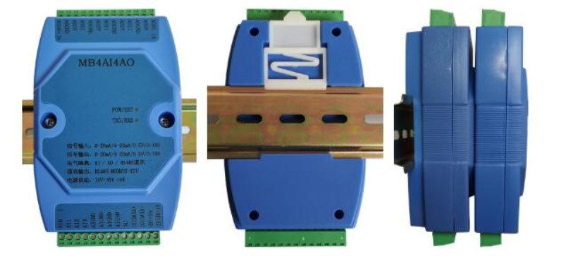
The front side of the rail installation The back side of the rail installation The effect of stacking and installation of modules Side
- Typical application wiring diagram
Thermocouple (J, K, T, E, R, S, B, N) and voltage input (±15mV,±100mV,±1V)wiring

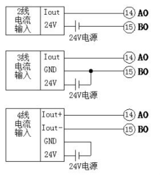
±20mAWiring with 4-20mA current input
PT100, PT1000, CU50, CU100 thermal resistance input wiring

RS485Communication wiring diagram
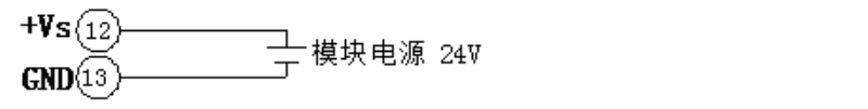
Module power input wiring
- Various signal input
- Thermocouple input
All channels can be directly connected to the thermocouple input, and the collected results can be directly converted into the actual temperature value. The built-in cold junction compensation sensor can automatically cold junction compensation for the thermocouple.
8 types of thermocouples, including J, K, T, E, R, S, B, N, etc. can be selected, and the corresponding channel is set to the corresponding thermocouple type when in use.
The temperature data result is a 16-bit signed int type, and the actual temperature is the actual temperature after dividing the read data by 10.
It has the function of detecting the disconnection of the thermocouple. If the disconnection of the thermocouple is detected, the channel value will be set to 30000. The disconnection status can also be queried for the sensor online status registers 1000110008.
Correspondence between measuring temperature range of thermocouple and specific data
Thermocouple type | Modbus RTUdata | Actual temperature value |
J(-2001200) | -2000~12000 | -200.01200.0 |
K(-2001370) | -2000~13700 | -200.01370.0 |
T(-200400) | -2000~4000 | -200.0400.0 |
E(-200950) | -2000~9500 | -200.0950.0 |
R(-201750) | -200~17500 | -20.01750.0 |
S(-201750) | -200~17500 | -20.01750.0 |
B(6001800) | 6000~18000 | 600.01800.0 |
N(-2501300) | -2500~13000 | -250.01300.0 |
- Platinum resistance input
All channels can be directly connected to the thermal resistance input, and can be connected to 2-wire and 3-wire temperature sensors, and the collected results are directly converted into actual temperature values.
4 types of thermal resistances, such as PT100, PT1000, CU50, CU100, can be selected, and the corresponding channel is set to the corresponding thermocouple type when in use.
The temperature data result is a 16-bit signed int type, and the actual temperature is the actual temperature after dividing the read data by 10.
It has the function of detecting the disconnection of the thermocouple. If the disconnection of the thermocouple is detected, the channel value will be set to -10000 or 30000. The disconnection status can also be queried in the sensor online status registers 1000110008.
Correspondence between the measuring temperature range of thermal resistance and specific data
Thermal resistance type | Modbus RTUdata | Actual temperature value |
PT100(-200850) | -2000~8500 | -200.0850.0 |
PT1000(-200850) | -2000~8500 | -200.0850.0 |
CU50(-50150) | -500~1500 | -50.0150.0 |
CU100(-50150) | -500~1500 | -50.0150.0 |
- Current input
All channels can be directly connected to ±20mA, 4-20mA current input, and the collected results are directly converted into actual current values. Please insert the jumper caps of the corresponding channels on the internal circuit board of the module when using.
±20mA and 4-20mA current signals can be selected, and the corresponding channel is set to the corresponding current type when in use.
The current data result is a 16-bit signed int type, and the actual current is the actual current after the read data is divided by 1000.
4-20mAThe input has the function of detecting the disconnection of the thermocouple. When the input current is lower than 2mA, it is judged that the bit is disconnected. The disconnection status can be queried in the sensor online status register 1000110008.
Correspondence between current measurement temperature range and specific data
Current type | Modbus RTUdata | Actual current value |
±20mA | -20000~20000 | -20.00020.000mA |
420mA | 4000~20000 | 4.00020.000mA |
- Voltage input
All channels can be directly connected to ±15mV, ±100mV, ±1V voltage input, and the collected results are directly converted into actual voltage values.
The current signals of ±15mV, ±100mV and ±1V can be selected, and the corresponding channel is set to the corresponding voltage type when in use.
The voltage data result is a 16-bit signed int type, and the data after reading passesThe following tableThe written magnification is calculated as the actual voltage.
Correspondence between voltage measurement range and specific data
Thermocouple type | Modbus RTUdata | Actual voltage value | Magnification |
±15mV | -15000~15000 | -15.00015.000mV | 1000 |
±100mV | -10000~10000 | -100.00100.00mV | 100 |
±1V | -10000~10000 | -1.00001.0000V | 10000 |
Q1: What Is Your Product Warranty?
A: We Guarantee Our Product Is Fit For Its Normal User Purposes And Is Free From Defects In Materials Or Workmanship.
Q2: What Is Your Company Policy On Defective Goods?
A: Our Company Keep Items Quality For A Long Time. If There Are Any Defective Goods Due To
Production Defects Or Transportation Problem, Please Contact Us. Our Customer Service Team Will Provide Immediate Response To
Complaints. We Will Try Our Best To Give You A Good Resolve Way.
Q3: What Is Your MOQ (minimum Order Quantity)?
A: Generally Our Moq Is No Limited. Please Have More Discussion With Us If Your Combination Of Models Is Complicated.
Q4:how About Getting Samples From You?
A: We Will Send You The Samples After We Receive The Payment For Samples. The Buyer Shall Afford The Shipping Cost. Please Have A
Confirm With Us Which Shipping Way Do You Want.
Q5:about The Shipment: What Type Of Shipment Will You Use?
A: We Usually Ship The Products By Express(delivery It To Your Door) Or By Air Freight To Your Nearest Airport, Shipping Days:3-7
Working Days Depend On Destination;if The Order Quantity Is Large, We May Ship By Sea Container And The Best Ship Way Is By Sea,
Shipping Days: Over 20 Working Days Depend On Destination Port.
Q6:what Packing Do You Use?
A: Neutral Package With Airbag Or Customized Package.
Q7:how Much Are The Shipping Cost?
A:shipping Cost Is Charged By The Package's Weight And Related To The Shipping Methods You Choose And Your Destination.
Q8:how To Order?
Step1.Click (Add to Cart) Buy Directly On The Product Page, Or Add To Shopping Cart And Settle Together, Pay With Paypal,
Need your information, such as full name,country, city, detail address, post code, tax number ...
Step2. We Will Delivery by EMS POST, FedEx or DHL Within
3-5 Working Days After Payment Confirmed.
Setp3. Confirm Us Receipt of Products.

