Brand Name:icchipcn.com
Condition:New
Type:Logic ICs
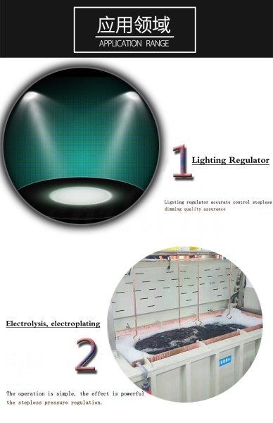
Rectifier and voltage regulation
Oversized Compatible Input: 180Vac -430Vac
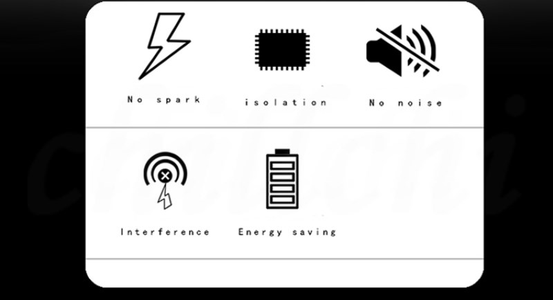
Built-in RC buffer - opto-isolated
Random on-random trigger

Product parameters:
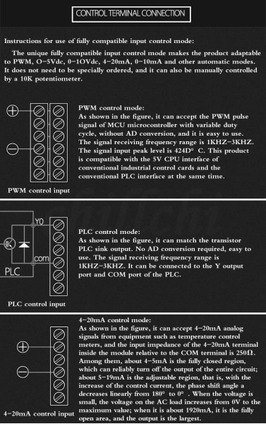
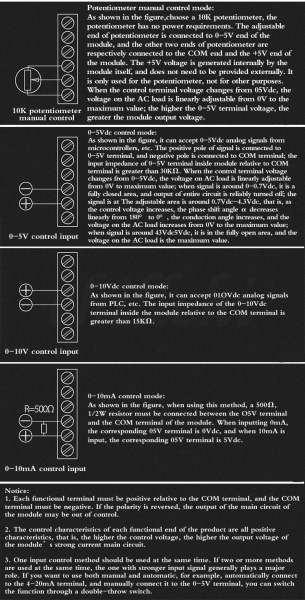
Input voltage control: 0-5V, 0-10V
Input current control: 4-20mA, 0-10mA
Input frequency duty cycle control: PWM: frequency 1kHz-3kHz, peak value 4-24Vdc
Manual potentiometer control: 10kΩ
LED indication: POW, OUT, indicator light
Rated working voltage: 220/380Vac
Grid frequency: 50Hz
Inrush current: 800%
Minimum load current: 100mA
Off-state leakage current: <12mA
Static voltage rise rate dVs/dt: >200us (enhanced)
Commutation voltage rise rate dVc/dt: >200us (enhanced)
Adjustment response time: <10ms
Turn off maximum delay: <10ms
Dielectric withstand voltage (between input, output and shell): ≥2000Vac
Insulation resistance (between input, output and shell): >1000MΩ (500Vdc)
Working environment temperature>1000MΩ (500Vdc):-40℃—+60℃
LSC-series integrated single-phase rectifier and voltage regulator module
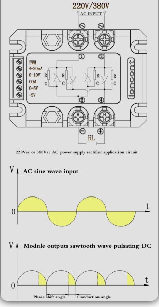
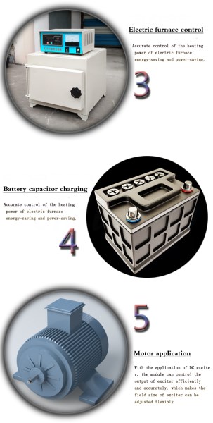
? ? ? ?The internal set of single-phase phase-shift trigger circuit, four-way one-way thyristor composed of full-control bridge four-way RC resistance-capacitance absorption circuit and power supply circuit are equal to one, under the action of automatic or manual adjustment input control, can change the conduction The strong trigger pulse signal of the angle then controls the internal thyristor separately to realize the direct conversion of the alternating current into the pulsating DC voltage with stepless adjustable amplitude, and the voltage on the load can be adjusted in a full range from 0V to the full voltage of the power grid. Modules are typically used in various power supply, voltage regulation, excitation, welding, electroplating, charging and other occasions.
Wiring diagram of the main circuit of strong electricity:
①③ is the AC input terminal
② is the output DC negative pole
④ is the output DC positive pole