Condition:New
Type:Logic ICs
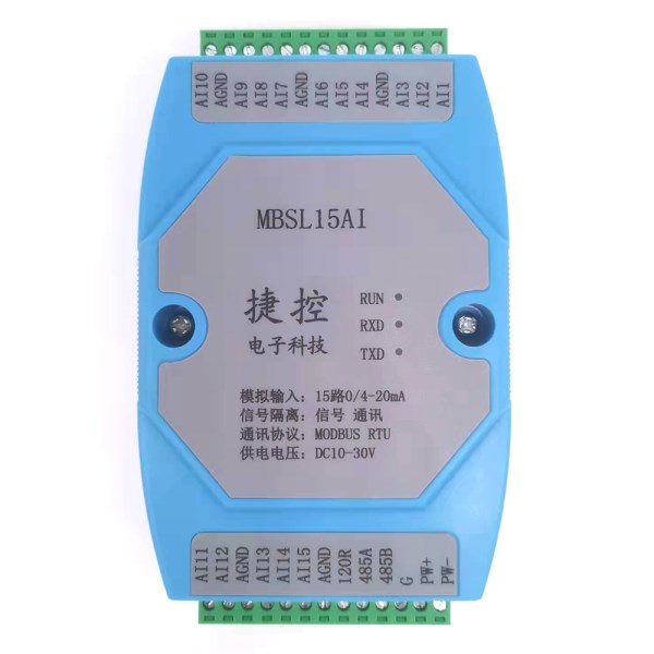
Model Number:MBSL15AI
1.Product overview
The MBSL15AI module is a 15-channel analog acquisition module, which can collect 15 commonly used 4-20mA analog signals. The collected analog signal data is output through the isolated RS485 interface. The module adopts standard Modbus RTU communication, which can be directly adapted to various upper computer configuration software, PLC, DCS,etc. Signal acquisition, power supply, and RS485 communication electrical signals are isolated from each other, effectively suppressing various series-mode and common-mode interference, ensuring data accuracy, and ensuring the stable and reliable operation of the module.
1. 15 single-ended analog inputs (DC type 4-20mA), using 12-bit industrial-grade AD acquisition chip
2. Using RS485 MODBUS RTU standard communication, it can be networked with the host computer configuration software, PLC, industrial
touch screen, etc., with communication status indicators
3. Signal acquisition, power supply, and RS485 communication electrical signals are isolated from each other.
4. The communication circuit adopts lightning protection and anti-interference design
5. The RS485 communication signal output interface adopts double overvoltage and overcurrent protection.
6. It can be widely used in signal acquisition and control of industrial field equipment.
7. The communication format can be set by software, and the module can be restored to factory settings by long pressing the
"button" on the back of the module for 3 seconds.
8. Power polarity protection
2、Main Specifications
Item | Technical indicators |
Signal
input | 1. Analog input channel: 15-channel
isolated acquisition 2. Analog input type: 4-20mA analog signal 3. Analog input accuracy: ±0.2 4. Operating temperature range: -20~70℃ 5. Resolution: 12bit 6.
External power supply: DC 9V~30V/2W |
Communication
output | 1.
Communication protocol: MODBUS-RTU 2. Interface
type: isolated RS485 communication, output interface adopts overvoltage and
overcurrent double protection 3. Baud
rate: 4800bps, 9600bps, 19200bps, 38400bps, 57600bps, 115200 4. Parity
bit: no parity, even parity, odd parity 5. Setting
method: module address, baud rate, check digit can be set by software 6.
Communication distance: @9600bps 1200 meters |
Module
size and installation method | 1. Installation method: standard DIN rail installation
or screw installation 2. Dimensions: 125×73×35mm |
Working
environment | Temperature:
-10~+55℃ Humidity: 35~85% (non-condensing) |
Working
power | 1. Power
supply voltage: 10V ~ 30V wide range power supply, with power supply polarity
protection 2. Power
consumption: less than 3W |
3、Interface definition
PW+ | External power input positive
terminal | AGND | Analog input negative terminal |
PW- | External power input negative
terminal | AI10 | The 10th channel analog input positive terminal |
AI1 | The 1st channel analog
input positive terminal | AI11 | The 11th channel analog
input positive terminal |
AI2 | The 2nd channel analog
input positive terminal | AI12 | The 12th channel analog
input positive terminal |
AI3 | The 3rd channel analog
input positive terminal | AGND | Analog input negative terminal |
AGND | Analog input negative terminal | AI13 | The 13th channel analog
input positive terminal |
AI4 | The 4th channel analog
input positive terminal | AI14 | The 14th channel analog
input positive terminal |
AI5 | The 5th channel analog
input positive terminal | AI15 | The 15th channel analog
input positive terminal |
AI6 | The 6th channel analog
input positive terminal | AGND | Analog input negative terminal |
AGND | Analog input negative terminal | 120R | 120 ohm matched resistor |
AI7 | The 7th channel analog input positive terminal | 485A | RS485 signal A+ |
AI8 | The 8th channel analog
input positive terminal | 485B | RS485 signal B- |
AI9 | The 9th channel analog
input positive terminal |
|
|
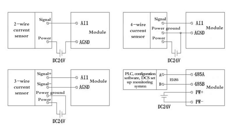
4.Analog input schematic diagram
5、Communication description
???
1、Communication parameter description (factory value):
9600, N, 8, 1
Parameter | Explain |
9600 | Baud rate |
N(None check) | Check bit |
8 | Data bit |
1 | Stop bit |
Chapter two?Modbus register and communication protocol description
6.Modbus function code and address range
Register
type | Address
Range | Function
code | Function
code Explain |
Input
register | 30001-30015 | 0x04H | Read one or more input registers |
Holding
register | 40001-40022
| 0x03H | Read one or more holding registers |
0x06H | Write a data to the holding register |
0x10H | Write one or more data to holding registers |
7.Register Definition Description
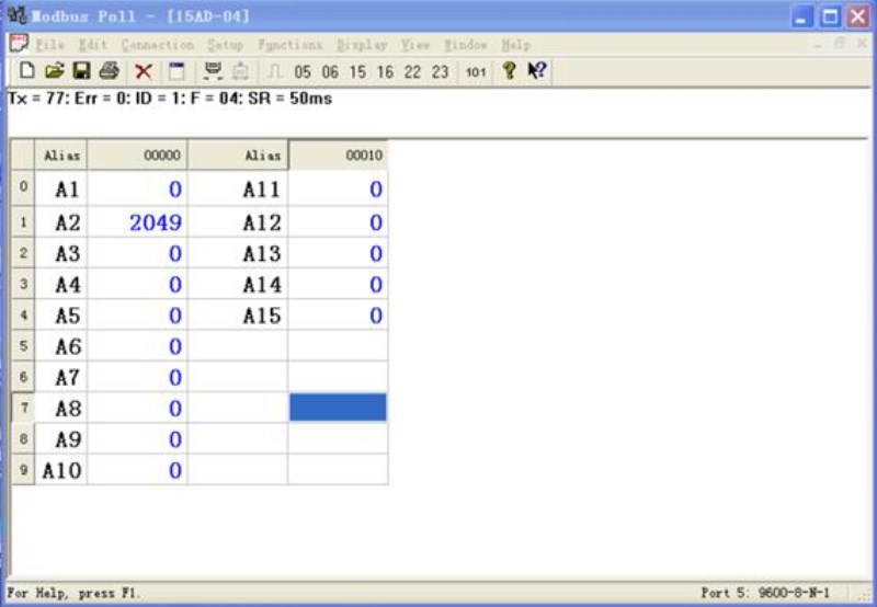
1.Input register (function code: 0x04H)
Address | Parameter | Length | Read/Write | Minimum | Maximum | Explain |
30001 | AI1 | 2 | Read
Only | 0 | 4095 | Analog input channel 1 AD converted value |
30002 | AI2 | 2 | Read
Only | 0 | 4095 | Analog input channel 2 AD converted value |
30003 | AI3 | 2 | Read
Only | 0 | 4095 | Analog input channel 3 AD converted value |
30004 | AI4 | 2 | Read
Only | 0 | 4095 | Analog
input channel AD converted value |
30005 | AI5 | 2 | Read
Only | 0 | 4095 | Analog input channel 5 AD converted value |
30006 | AI6 | 2 | Read
Only | 0 | 4095 | Analog input channel 6 AD converted value |
30007 | AI7 | 2 | Read
Only | 0 | 4095 | Analog input channel 7 AD converted value |
30008 | AI8 | 2 | Read
Only | 0 | 4095 | Analog input channel 8 AD converted value |
30009 | AI9 | 2 | Read
Only | 0 | 4095 | Analog input channel 9 AD converted value |
30010 | AI10 | 2 | Read
Only | 0 | 4095 | Analog input channel 10 AD converted value |
30011 | AI11 | 2 | Read
Only | 0 | 4095 | Analog input channel 11 AD converted value |
30012 | AI12 | 2 | Read
Only | 0 | 4095 | Analog input channel 12 AD converted value |
30013 | AI13 | 2 | Read
Only | 0 | 4095 | Analog input channel 13 AD converted value |
30014 | AI14 | 2 | Read
Only | 0 | 4095 | Analog input channel 14 AD converted value |
30015 | AI15 | 2 | Read
Only | 0 | 4095 | Analog input channel 15 AD converted value |
2.Holding register
(function code: 0x03H, 0x06H, 0x10H)
Address | Parameter | Length | Read/Write | Minimum | Maximum | Explain |
40009 | AI1 | 2 | Read
Only | 0 | 4095 | Analog input channel 1 AD converted value |
40010 | AI2 | 2 | Read
Only | 0 | 4095 | Analog input channel 2 AD converted value |
40011 | AI3 | 2 | Read
Only | 0 | 4095 | Analog input channel 3 AD converted value |
40012 | AI4 | 2 | Read
Only | 0 | 4095 | Analog input channel 4 AD converted value |
40013 | AI5 | 2 | Read
Only | 0 | 4095 | Analog input channel 5 AD converted value |
40014 | AI6 | 2 | Read
Only | 0 | 4095 | Analog input channel 6 AD converted value |
40015 | AI7 | 2 | Read
Only | 0 | 4095 | Analog input channel 7 AD converted value |
40016 | AI8 | 2 | Read
Only | 0 | 4095 | Analog input channel 8 AD converted value |
40017 | AI9 | 2 | Read
Only | 0 | 4095 | Analog input channel 9 AD converted value |
40018 | AI10 | 2 | Read
Only | 0 | 4095 | Analog input channel 10 AD converted value |
40019 | AI11 | 2 | Read
Only | 0 | 4095 | Analog input channel 11 AD converted value |
40020 | AI12 | 2 | Read
Only | 0 | 4095 | Analog input channel 12 AD converted value |
40021 | AI13 | 2 | Read
Only | 0 | 4095 | Analog input channel 13 AD converted value |
40022 | AI14 | 2 | Read
Only | 0 | 4095 | Analog input channel 14 AD converted value |
40023 | AI15 | 2 | Read
Only | 0 | 4095 | Analog input channel 15 AD converted value |
|
40003 | Device
Address | 2 | Read/Write | 1 | 247 | 1(Default) |
40004 | Baud
rate | 2 | Read/Write | 1 | 5 | 1(4800) 2(9600)默认3(19200) 4(38400)? 5(57600)? 6(115200) |
40005 | Check
bit | 2 | Read/Write | 1 | 3 | 1 (no parity.) Default 2 (odd parity) 3 (even parit) |
40007 | Productversion | 2 | Read
Only | 0 | -- | Year + Month + Day |
8.Conversion of channel sampling values to actual data calculation
method
1. 4-20mA input: actual value = ((collected value
(decimal form)-819)*(20-4)/(4096-819))+4
For example: if channel 0 is set to 4-20mA input, the
data read by communication is 0x07D0H, the conversion decimal is 2000, and the
calculation formula is: ((1181*16) / 3277) +4= 9.76mA
Note:
"Acquisition value" is the original digital value, "Actual
value" is the converted actual current value. In practical application,
the 20mA here can also be changed to the upper limit of the engineering
quantity.
Chapter three Product configuration
9.Communication settings
1.Default factory communication parameters
Item | Register
address | Explain | Default
value |
Address | 40003 | 1(Default) | 1 |
Baud
rate | 40004 | 1(4800)2(9600)Default3(19200) 4(38400) 5(57600)?6(115200) | 2 |
Check
bit | 40005 | 1 (no parity.) Default 2 (odd parity) 3
(even parity) | 1 |
Data
bit | --- | Not adjustable | 8
bit |
Stop bit | --- | Not adjustable | 1 bit |
2.Reset communication parameters
1. In order to prevent the user from
forgetting the set communication parameters, it is impossible to communicate
with the module. The recovery initialization function is specially designed.
2. Use a toothpick to press and hold the
"button" on the back of the module for more than 3 seconds, until the
"RUN" red indicator light of the module flashes and release the
pressed button, the RUN indicator flashes 3 times and then returns to steady
light (running state) Factory settings. Then the communication parameters have
been reset to the default values after the module is powered off and powered on
again.
2、Communication indicator
description
1. After the module is powered on, the red
working indicator "RUN" of the module is always on, and when the
reset button is pressed, it will flash three times at 1-second intervals.
2. During module communication, the
communication indicator flashes according to the received data "RXD&

