Condition:New
Type:Logic ICs
Model Number:Constant voltage output
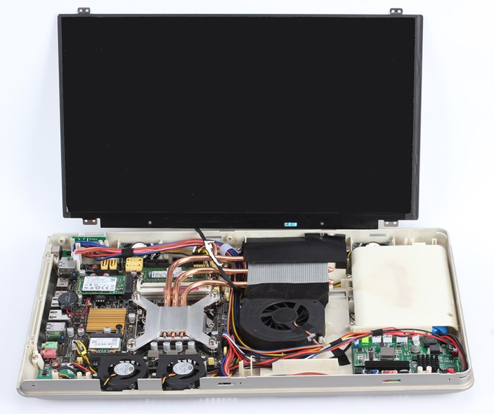
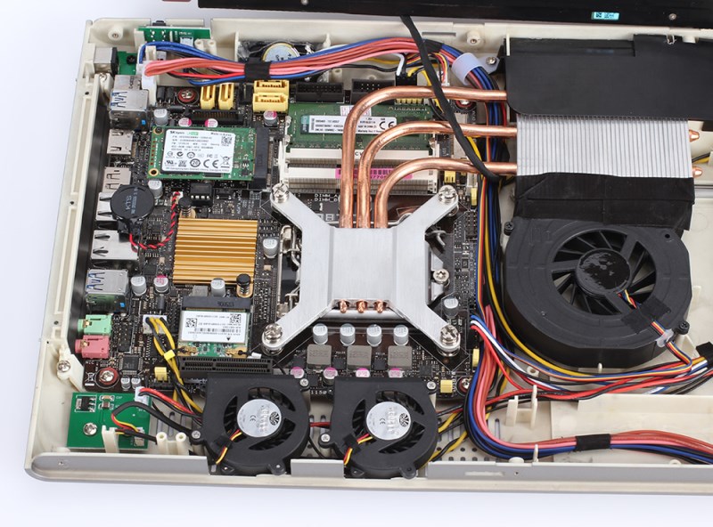
? ? ? ? If you use industrial computer motherboards or desktop motherboards for rugged computers, portable computers, or embedded devices, and you need to install batteries for mobile use, then there is a problem that cannot be avoided. It is the problem of the voltage and power collection and display of the lithium battery. Since desktop computers have no I2C interface, and ordinary lithium battery protection boards have no USB interface, how to display the remaining power of the system has always been a problem. The current solutions generally use LED indicator lights or add LED voltage acquisition and display modules. This method is not intuitive, the accuracy is low, and there is no grade. The fourth is the inability to add management functions. This program is perfect to solve the above problems. The battery level displayed in the system is as shown in the figure below. The program can be hidden in the taskbar.

If it is powered by a battery, there is another problem that cannot be avoided is the one-button boot of the system. If the power button is directly led out, the consequence is that the system battery will be completely drained within one or two days after the power is turned off. Because the motherboard consumes too much power. Therefore, the power supply must be completely disconnected from the motherboard when the system is shut down. This requires a comprehensive takeover of the switch machine circuit. This module completely solves the above problems.
The basic parameters of the circuit board are as follows:
If the battery is 3 strings, the adapter input voltage is 13.5V-24V
The output voltage is adjustable from 12V-24V (the output voltage is a constant voltage mode, that is, the adapter can use a 19V adapter, and the output is 12V constant voltage)
The stable output current is 8A, and the limit is 9.5A. If it exceeds 6A, a fan is required to dissipate heat.
The battery charging method is constant current first, then constant voltage.
Working mode: Detect the power of the system once every second, and communicate with the motherboard through the serial port.
Working principle: After pressing the power button, the voltage management board is first powered on to work. After 1 second, the power supply circuit for the motherboard is turned on. At this time, the motherboard is electrified. Then turn on the motherboard power-on button to turn on the motherboard. When the system is turned off, the power board detects that the motherboard is turned off, and automatically powers off after *3 seconds. When it is detected that the motherboard is in a hibernation state, the shutdown operation is not performed. When the power button 5 is pressed for a long time, the power is completely cut off.
Application:
The circuit board is equipped with an automatic step-up and step-down module. If the output voltage is set to 12V, the battery voltage will be automatically boosted to 12V when the battery voltage is less than 12V, and if the adapter voltage is 19V, the voltage will be automatically stepped down to 12V. The voltage difference between the battery and the adapter is more than 1V. Otherwise, automatic switching cannot be realized or the charging is not full.
The working efficiency of the circuit board is very high, and it is basically the same as the body temperature when the output is below 3A. The highest efficiency can reach 98%, and the efficiency is also above 92% when the power is output.
Customize Function(Need pay extra cost):
The board size is 110*65*18. In addition to basic power management functions, the circuit board also supports a 2.2-inch LED LCD screen display, 2 channels of temperature acquisition, 4 channels of PWM signal output, and 2 channels of key input. These accessories are not equipped by default, and the software of the circuit board does not support these functions. These functions are specially designed for customized customers. The function of the LCD screen is to display information about the remaining battery capacity without looking at the computer or turning on the computer, whether the adapter is plugged in, and how many degrees the temperature is collected for the two channels. For example, it is also possible to use the module on an embedded device. Programs can be written according to the environment and requirements. For example, when the temperature tested by temperature probe 1 is greater than 30, the speed of fan 1 and 2 is increased to 50%, when the temperature is greater than 50 degrees, the maximum is increased, and when the temperature tested by temperature probe 2 is greater than 50 degrees, the output will be turned off. The temperature drops and then restarts, or the entire system is powered off, etc.

