Brand Name:icchipcn.com
Condition:New
Type:Logic ICs
Overview
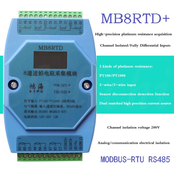
MB8RTD 8-channel high-precision platinum resistance temperature acquisition module, can collect 2 kinds of platinum resistance (PT100, PT1000), can match 2-wire or 3-wire connection; platinum resistance excitation source is dual-matching programmable excitation current source, acquisition accuracy and speed Higher and faster; and has the function of automatic detection of platinum resistance disconnection, which is convenient for on-site debugging and maintenance. The collected analog signal data is output through the isolated RS485 interface; the module adopts Modbus-RTU communication, which can be adapted to PLC, DCS and various configuration software.
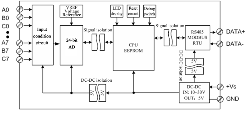
Signal input, CPU, power input and RS485 communication electrical signals are isolated from each other, effectively suppressing various series-mode and common-mode interference, ensuring the accuracy of data, and also ensuring the reliable operation of the module.
The module is mainly used in applications where temperature acquisition and multiple analog input signal types coexist. It can be widely used in steel smelting, metal heat treatment, chemical industry, metallurgy, glass processing, injection temperature control, tobacco, medicine, complete sets of automation equipment and so on.
Product Features
● 8-channel platinum resistance input (each channel can be freely selected: PT100, PT1000, 2 kinds of signals), you can set the platinum resistance type of the channel according to your own needs.
● With 0.96-inch OLED display, it can display the value of each channel in real time, which is convenient for on-site maintenance and installation.
● The platinum resistance input has the function of automatic disconnection detection, which is convenient for on-site debugging and maintenance.
● Fully differential input, and each channel is electrically isolated from each other.
● High-precision signal acquisition: high-precision 24-bit AD and voltage reference are used, and the temperature coefficient of the voltage reference is 10PPM/℃.
● The platinum resistance excitation source is a dual-matching programmable excitation current source, and the acquisition accuracy and speed are higher and faster.
● Safety: signal acquisition, power supply, RS485 communication, and electrical signals are isolated from each other.
● Adopt standard Modbus-RTU protocol, RS485 communication signal output interface adopts double overvoltage and overcurrent protection.
● Input signal type and communication format can be set by software.
● Protection: signal input overvoltage protection, power input polarity protection and overvoltage protection, RS485 double overvoltage and overcurrent protection.
Technical indicators
Item | Parameter |
AI Signal | 1. Input channels: 8 differential inputs, each input channel is isolated from each other, isolation voltage: 200V 2. Input signal type: 2 types of platinum resistance (PT100, PT1000) 3. Setting method: set by software 4. Scanning period: 8 channels are collected every 500mS. 5. AD resolution: 24 bits. 6. Signal acquisition circuit and power input isolation voltage protection: 1000V |
RS485 Communication output | 1. Communication protocol: standard MODBUS-RTU RS485. 2. Communication distance: @9600bps 1200 meters. 3. Communication medium: ordinary twisted pair, greater than or equal to 0.5mm2. 4. Interface type: isolated RS485 communication, the output interface adopts double protection of overvoltage and overcurrent. 5. Baud rate: 1200, 2400, 4800, 9600, 19200, 38400, 57600, 115200bps. 6. Check digit: no check, even check, odd check. 7. Data bit and stop bit: 8 data bits, 1 stop bit, these two parameters are not adjustable. 8. Power input and RS485 circuit isolation voltage protection: 1000V. 9. Setting method: module address, baud rate, check digit can be set by software. |
Module size | L104mm * H72mm * H26mm? |
Installation method | Standard 35mm DIN rail mounting |
Working environment | 1. Temperature: -20 ~ +60℃ 2. Humidity: 35 ~ 85%
(non-condensing) |
Working power | 1. Power supply voltage: 10V ~ 30V wide range power supply, with power supply polarity protection 2. Power consumption: less than 2W |
Measurement accuracy | Input type | Measure range | Display resolution | Precision |
Platinum resistance | PT100(-200~850℃) | 0.1℃ | ±0.1FS |
PT100(-200~850℃) | 0.1℃ | ±0.1FS |
·Terminal definition and status indication
1.Terminal Definition
Terminal | Name | Explain |
| Terminal | Name | Explain |
1 | A5 | Platinum resistance Input channel 5 positive terminal | 26 | C4 | Platinum resistance input C4 |
2 | B5 | Platinum resistance Input channel 5 negative terminal | 25 | B4 | Platinum resistance Inputchannel 4 negative terminal |
3 | C5 | Platinum resistance input C5 | 24 | A4 | Platinum resistance Inputchannel 4 positive terminal |
4 | A6 | Platinum resistance Input channel 6 positive terminal | 23 | B3 | Platinum resistance Inputchannel 3 negative terminal |
5 | B5 | Platinum resistance Input channel 6 negative terminal | 22 | A3 | Platinum resistance Inputchannel 3 positive terminal |
6 | C6 | Platinum resistance input C6 | 21 | C23 | Platinum resistance input C23 |
7 | A7 | Platinum resistance Input channel 7 positive terminal | 20 | B2 | Platinum resistance Inputchannel 2 negative terminal |
8 | B7 | Platinum resistance Input channel 7 negative terminal | 19 | A2 | Platinum resistance Inputchannel 2 positive terminal |
9 | C7 | Platinum resistance input C7 | 18 | B1 | Platinum resistance Inputchannel 1 negative terminal |
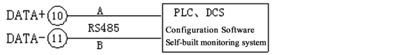
10 | DATA+ | RS485 A communication + | 17 | A1 | Platinum resistance Inputchannel 1 positive terminal |
11 | DATA- | RS485 B communication - | 16 | C01 | Platinum resistance input C01 |
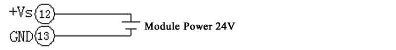
12 | +Vs | Power input + | 15 | B0 | Platinum resistance Inputchannel 0 negative terminal |
13 | GND | Power input - | 14 | A0 | Platinum resistance Inputchannel 0 positive terminal |
1.3.?
?Module Indicator Description
?A.
POW/SET; module working status indication
Green light on: The module is working in the running state.
Red light on: the configuration parameters of the module have been written and taken effect, and the CPU of the module will automatically reset and restart.
1.
B. TXD/RXD: Communication status indication
Blinking green light: Communication has received data, but no data is returned.
Alternately flashing green and red: The module is receiving and sending data.
Green light is always on: the communication RS485 lines connected to DATA+ and DATA- are reversed or the
connection is broken.
2.4.?Function description of the reset switch on the right side of the
module
·1. A. Communication
parameters after delivery and reset: address: 1, baud rate: 9600bps, parity bit: none.
·2. B. When the
communication parameters (module address, baud rate, check digit) are unknown or the communication parameters are set incorrectly, and the communication with the module cannot be established, the solution is to reset the communication parameters; we use a paper clip to press and hold the reset If the switch is not
released, the module [POW/SET] red indicator will be on after 5 seconds.
Release the reset switch. At this time, the communication parameters have been reset, the CPU of the module will automatically reset and restart, and the POW and other lights will be green.
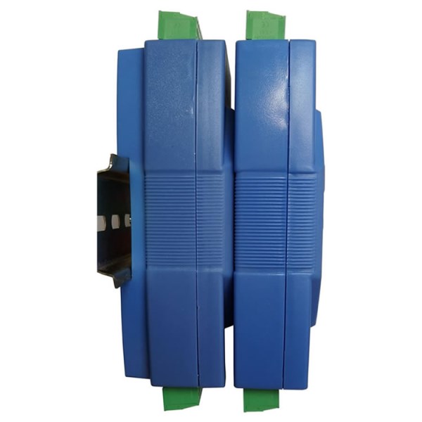
? Module installation method: rail installation
·Typical application
wiring diagram
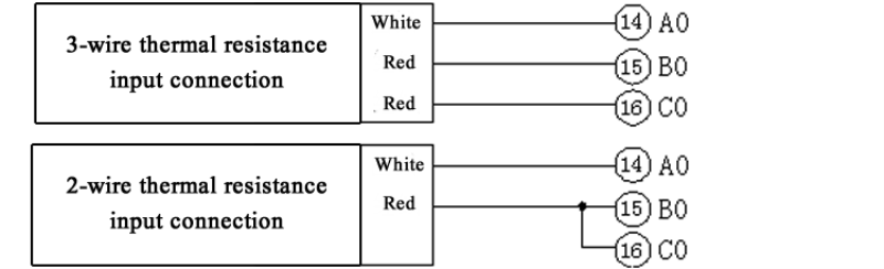
·PT100、PT1000 RTD input wiring
1.? 2. RS485 Communication wiring diagram
? ?3.?Module Power InputWiring
·Various signal inputs
·Platinum resistance input
? All channels can be directly connected to thermal resistance input,and 2-wire and 3-wire temperature sensors can be connected, and the collected results can be directly converted into actual temperature values.
? Two types of thermal resistances such as PT100 and PT1000 can be selected, and the corresponding channel can be set to the corresponding thermalresistance type according to the needs.
? The result of the temperature data is a 16-bit signed int type. The read data is divided by 10 to obtain the actual temperature.
? It has the function of detecting the disconnection of the thermalresistance. If the disconnection of the thermal resistance is detected, thechannel value will be set to -30000 or 30000. The disconnection status can also query the sensor online status registers 10001~10008.
? The measurement temperature range of thermal resistance and the corresponding relationship of specific data.
RTD Type | Modbus RTU Data | Actual temperature value |
?PT100(-200~850℃) | -2000~8500 | -200.0~850.0℃ |
PT1000(-200~850℃) | -2000~8500 | -200.0~850.0℃ |
·Schematic Block Diagram