Condition:New
Type:Logic ICs
PT100/PT1000 four channel platinum resistance acquisition module, 4 channels can be collected from the same input type platinum resistance, each channel can also input different platinum resistance; full range acquisition range of -200-850 degrees, the display accuracy of 0.1 degrees, acquisition accuracy of 0.05%. and 4 road and 4 road opened. Communication using MODBUS-RTU RS485; can be adapted to PLC, DCS and a variety of configuration software, etc.
Defualt setting is PT100,if need PT1000,please note.
The first chapter product introduction
A.Summary
MB4RTD4roadPlatinum resistance high precisionThe acquisition module, the platinum resistance (PT100/PT1000 385 double excitation current respectively 500uA/250uA) signal; excitation source for double platinum resistance, programmable excitation current source, acquisition speed and precision is higher and faster; analog signal data acquisition, by isolating the RS485 interface output; module using Modbus-RTU communication, can be adapted to PLC, DCS and configuration software.
Signal acquisition, CPU and power input, RS485 communication electrical signal isolation, the effective suppression of all kinds of serial mode and common mode interference, to ensure the accuracy of the data, but also to ensure the reliability of the module.
Two.Characteristic
1.Using standard Modbus-RTU protocol.
2.According to their own needs to set the input signal type channel.
ThreeHigh precision signal acquisition: using high precision 24 bit AD and dual excitation to match the programmable current source.
4.Security: signal acquisition, signal output, power supply, RS485 communication electrical signals isolated from each other.
FiveCommunication protection: RS485 communication signal output interface using overvoltage and over current dual protection.
SixInput signal type, communication format can be set through the software.
7.Power polarity protection.
Three.Technical index
project | parameter |
AI Signal input | 1Input channel: 4 channel isolated analog acquisition 2Input signal type: platinum resistance (PT100/PT1000) can be defined for each channel input 3Sampling rate: 4 channels per 200mS acquisition time (each channel 5 acquisition points per second) 4Resolution: 24 AD bit acquisition 5.Acquisition circuit and CPU isolation voltage protection: 1500V |
DIAnd DO | 1.4Dry contact input optocoupler Commons 2.4The way open collector output optocoupler Commons |
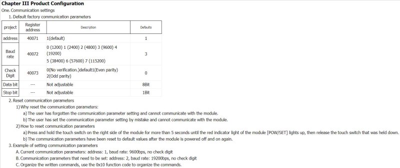
RS485 Communication output | 1Communication protocol: MODBUS-RTU 2Interface type: isolated RS485 communication, the output of the interface using the overvoltage and overcurrent protection 3Baud rate: 1200BPS, 2400bps., 4800bps, 9600bps, 19200bps 38400bps57600bps, 115200bps. 4Check bit: no parity check, parity check 5. setting: module address, baud rate, parity bits can be set by software 6.Communication circuit and CPU isolation voltage protection: 1500V |
Module size | A.Separate module size: 104mm*72mm*26mm B.With terminal and guide rail box size: 124mm*72mm*45mm |
Installation method | Standard DIN guide rail installation (35mm guide rail or high and low track) |
work environment | Temperature: -10 ~ +55 temperature humidity: 35~85% (not dew) |
Working power supply | 1Power supply voltage: 10V~30V wide range of power supply, with the power supply polarity protection 2Power consumption: less than 3W |
Four.measurement accuracy
Input type | measuring range | Display resolution | accuracy |
rtd | PT100(-200 - 850 degrees C) | 0.1C | 0.05% |
PT1000(-200 - 850 degrees C) | 0.1C | 0.05% |
Five.Product appearance
Six.Module indicator lamp and switch function specification
1.POW/SET;Module working status indication
A.Green light: the module works in the running state. B. red light: the module has the configuration parameters have been written, need to re power up.
2.TXD/RXD:Communication status indication
A.The green light flashes: the communication receives the data B. red light flashes: the module is sending data
C.The green light is always on: DATA+ and DATA- on the communication line RS485 line is connected to the reverse or the connection is broken
ThreeModule right reset switch
A.When the communication parameters (module address, baud rate, parity bit) do not know or communication parameter misspecification, and can not establish contact module communication, the solution is to reset the communication parameters; we use the clip to hold the reset switch is not open, 5 seconds after the [POW/SET] module of the red indicator lights, release the reset switch, the communication the parameters have been reset, as long as the power supply module after the restart time, the communication parameters of the module has been reset.
B.Communication parameters after reset: Address: 1, baud rate: 9600bps, parity: No.
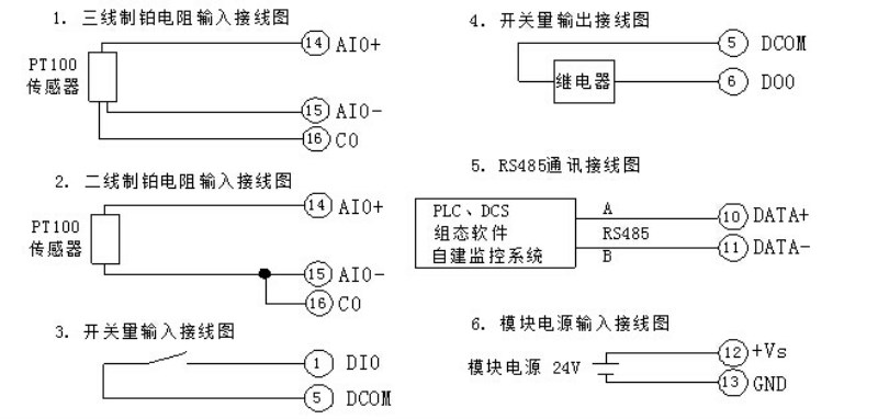
Seven.Typical application wiring diagram
Eight.Terminal definition
terminal | Name | Explain | | terminal | Name | Explain |
1 | DI0 | Switch input 0 | 26 | NC | empty |
2 | AIGND | Switch input 1 | 25 | C3 | Platinum resistance input 3 |
3 | IN1+ | Switch input 2 | 24 | AI3- | Analog input channel 3 negative |
4 | IN2+ | Switch input 3 | 23 | AI3+ | Analog input channel 3 positive |
5 | DCOM | Open in public | 22 | C2 | Platinum resistance input 2 |
6 | DO0 | Switch output 0 | 21 | AI2- | Analog input channel 2 negative |
7 | DO1 | Switch output 1 | 20 | AI2+ | Analog input channel 2 positive |
8 | DO2 | Switch output 2 | 19 | C1 | Platinum resistance input 1 |
9 | DO3 | Switch output 3 | 18 | AI1- | Analog input channel 1 negative |
10 | DATA+ | A RS485Communication + | 17 | AI1+ | Analog input channel 1 positive |
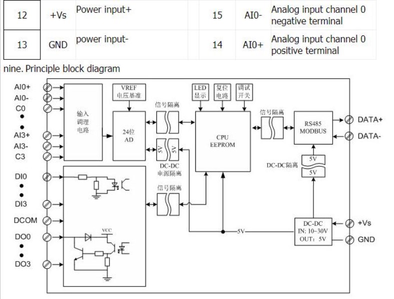
11 | DATA- | B RS485Communication - | | 16 | C0 | Platinum resistance input 0 |
12 | +Vs |