Brand Name:icchipcn.com
Condition:New
Type:Logic ICs
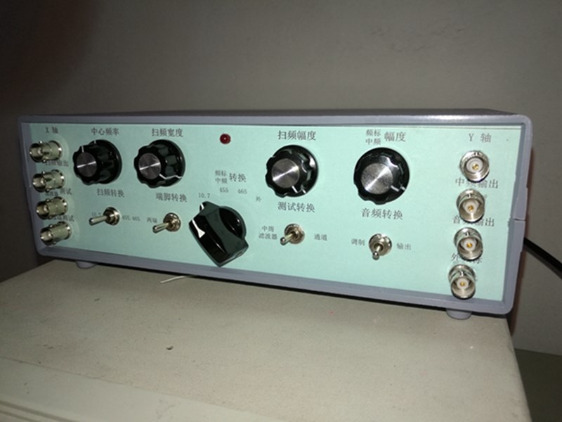
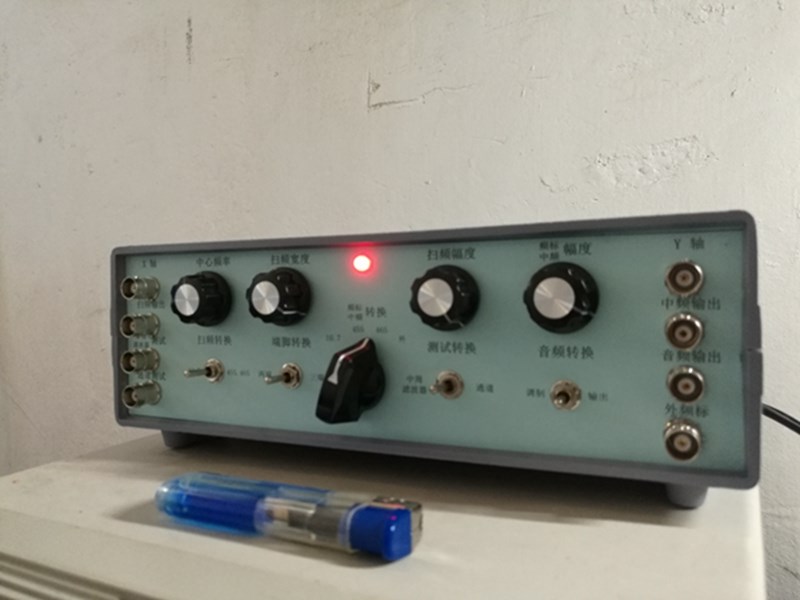
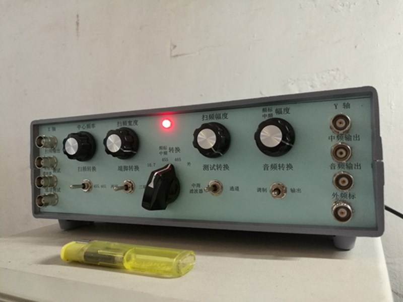
Note:this pannel is Chinese.
Compared with similar products onlne, this product has the following characteristics:
1. It has 455, 465 and 10.7 Crystal stabilized frequency standard, covering all intermediate frequencies of radio. Similar products have only two frequency points and are ordinary LC oscillations. The precision is very low and it is easy to run frequency. You need to open the chassis frequently for adjustment (you often need to remove four screws and open the upper cover, which annoys you to death) moreover, you cannot detect the values of the frequency scale and the center frequency from the panel. You also need to open the chassis.
2. The center frequency can be adjusted on the panel to easily return the center frequency of the sweep frequency to the center of the screen,similar products do not have the central frequency adjustment function, so the chassis should be opened frequently for adjustment (four screws should be removed frequently and the upper cover should be opened frequently, which annoys you so much)
3. The sweep width can be adjusted. You can observe the sweep curve under different sweep widths. Similar products do not have this function.
4. This product refers to the PCB printing board produced, with green oil resistance welding and tin plating on welding holes, which is easy to weld. The same kind of products are hand-made, without green oil resistance welding, and without welding holes and tin plating. They often Weld one piece at a time, which is not good-looking and easy to be short-circuited.

Radio frequency sweeper intermediate frequency signal generator audio signal generatorV3.0reinstall
V3.0 Update content (comprehensive optimization and update according to the problems pointed out by the user's actual installation and adjustment):
1. The diameter of the welding hole of the circuit board is expanded to 1mm, and all the core unit circuit boards adopt single panel, which is convenient for welding and debugging;
2. Correct bugs (errors) in the design;
3. Optimize some component parameters and make the schematic diagram and screen printing parameters of the printing plate strictly correspond one by one;
4, adjust the triode foot position silk screen layout, make the whole kit coordinated;
5. Added panel cable to the luxury suite;
frequency sweeper is a necessary tool for debugging shortwave and FM radio. Everyone who plays the radio knows that playing the radio is just playing inductance, but it is often these inductance and the Middle cycle that are the obstacles to debugging. In spare time, we can only debug by listening, which is very unreliable. Improper mid-cycle debugging will cause light sound and distortion, while heavy debugging will cause the machine to be silent. For this reason, our studio has introduced a Multifunctional testing instrument, one of which is the frequency sweep signal generator. With oscilloscope, the intermediate frequency can be accurately locked in465perhaps455perhaps10.7, debugging the perfect intermediate frequency curve can bring great satisfaction to us electronic fanatics both visually and visually. This instrument also has455/465/10.7intermediate frequency signal generator and1KHzaudio signal generator.
For more concentrated issues:
q: The installation is not difficult. Do I need to debug it? How long does it take to complete the installation?
A: The circuit diagram of this machine is not complicated. As long as you understand the circuit diagram and mark the component parameters according to the circuit board, you can basically install the components on the circuit board that do not need to be adjusted in half A day. This machine needs to be debugged, mainly to adjust the working point of the triode to the waveform amplitude, and the waveform shall prevail. According to my installation schedule, it takes three and a half days to install components, punch holes, debug, install panel connection and adjust the whole machine in half a day. Beginners may be slower. However, the author suggests that you should read the circuit diagram and installation instructions carefully first, so as to know fairly well, and the installation and debugging will be quick. On the contrary, if the principle is not clarified, if you don't read the installation instructions carefully, you will make some unexpected mistakes and waste time.
I. Basic parameters
(By Oscilloscope1/10measurement)
frequency sweep output voltage:
465/455KHz 0-6VAdjustable
10.7MHz 0-6VAdjustable
intermediate frequency (frequency standard) signal output voltage:
crystal frequency stabilization465KHz 0-6VAdjustable
crystal frequency stabilization455KHz 0-6VAdjustable
crystal frequency stabilization10.7MHz 0-6VAdjustable
audio signal output voltage:0-6VAdjustable
audio modulation:0-50%Adjustable
465/455center frequency:380-510KHzcontinuous adjustable, no need to open the chassis for debugging (this is very important, you will know when you use it)
10.7center frequency:8.5-11.5MHzcontinuously adjustable.
II. Features
1, yes465KHz,455KHzand10.7MHzdebug the intermediate frequency curve of the amplitude modulation and frequency modulation radio. (You don't have to worry about being transferred465or455, both can be used, the general professional frequency sweeper will also mention one455frequency point)
2, yes465KHz,455KHzand10.7MHzintermediate frequency transformer and frequency detector carry out intermediate frequency curve correction and quality inspection.
3, yes465KHz,455KHzand10.7MHz(Both ends and three ends) ceramic filter for quality inspection. What you see is what you get, very convenient.
4, inDIYRadio or adjust the intermediate frequency, as long as input465KHz(455) amplitude modulation intermediate frequency signal, you can accurately and quickly adjust the intermediate frequency of the amplitude modulation radio465KHz(455). In addition, the signal generator also outputs rich harmonic signals, and does not need a special high-frequency signal generator. The radio can receive them wirelessly by using harmonic waves. Because the crystal frequency is stabilized, the frequency is very accurate.
5, inDIYWhen FM radio or adjusting intermediate frequency, just input10.7MHzFM intermediate frequency signal can accurately and quickly adjust the intermediate frequency of FM radio10.7MHz。
6, this machine can produce1000Hzsine wave audio signal can conduct amplitude modulation and frequency modulation for intermediate frequency signal respectively. The signal injection method can be used to find the fault part of the low frequency amplification part of the radio and power amplifier, or the audio injection method can be used to detect and correct the waveform distortion of the power amplifier with oscilloscope when making the amplifier.
III. Design features
1, frequency standard and signal generator designed three frequency points:455K,465K,10.7M, almost all professional radios on the market only455and10.7two frequency points, and both adopt crystal frequency stabilization, the frequency is very accurate.
2, the center frequency can be adjusted on the panel, there is no need to open the chassis to adjust the middle week (465/455center frequency:380-510KHzcontinuously adjustable,10.7center frequency:8.5-11.5MHzcontinuous adjustable.) This is very important, you will know it after using it.
3. The sweep width can be continuously adjusted. You can debug the intermediate frequency curve under different sweep widths.
4For the stability of frequency, the frequency sweep instrument and its frequency standard circuit adopt independent structure respectively, (two channels of the frequency sweep instrument,455/465and10.7, frequency standard three channels, respectively using crystal frequency stabilization) and using power switch to control their respective working states, overcoming the high frequency leakage caused by switching high frequency oscillation coil with switch, problems such as frequency drift and high frequency self-excitation.
2In order to improve the linearity of the sweep frequency signalNE555as a sawtooth wave generator, output12Vserrated wave voltage with good linearity.
3. Each working unit board is made independently, which is convenient to be fixed in the corresponding position inside the machine, making full use of the space inside the chassis, avoiding the self-excitation and frequency drift phenomenon caused by too long signal line connection. At the same time, technical measures have been taken for the inevitable long-term connection.
4. It can test the mid-cycle and the filters at both ends and three ends, and it is very convenient to detect the mid-cycle and filters through switch conversion and Port socket output.
5, if in380-510KHzand8.5-11.5MHzfriends with special needs, this instrument also provides external frequency standard input function, you can input your own frequency standard signal into this instrument.
6The design of large case makes the instrument look more classy.
7, as can be seen from the above, the use method of this instrument is flexible and changeable, everything is alive, can be adjusted on the instrument panel, so as to make the accuracy of the instrument, available range, the combination of visual sense and the listening sense of the tested machine will give you psychological satisfaction.
8, this instrument must cooperate with oscilloscopeX-Yfunction usage.
full set of spare parts and accessories:including a full set of spare parts except for the resistance determined after debugging, chassis, manufactured printed pcb panel, transformer, a set of test cable, power line, instructions for use, debugging instructions, drawings, panel connecting line, free knob;
"Installed and debugged finished machine":? the whole machine is installed and debugged,installation and debugging instructions, instructions, drawings, free knob, a set of test Cable, the panel is the perforated silk-screen pcb panel.
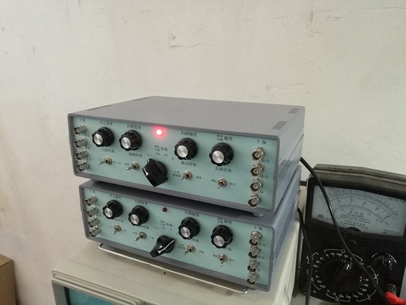
Physical picture:
Size: width255mm deep 191mm high 81mm
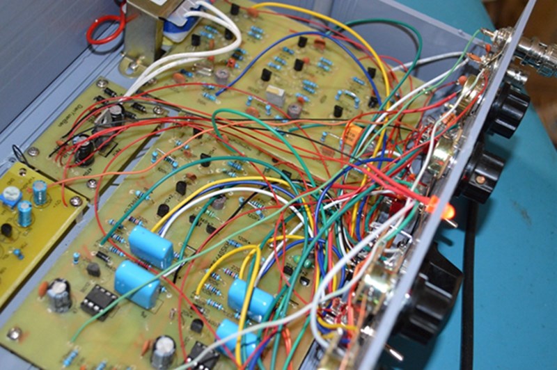
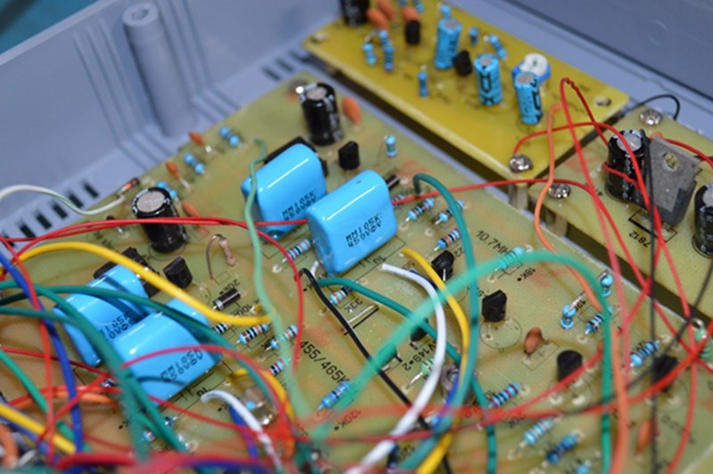
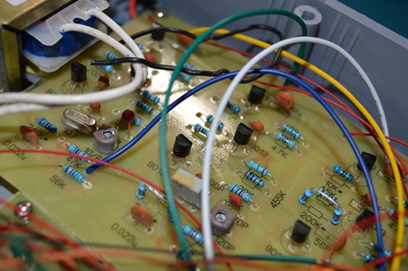
inside the frequency sweeper
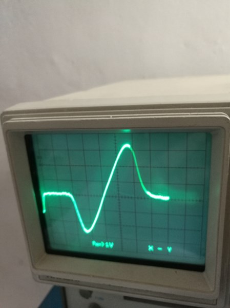
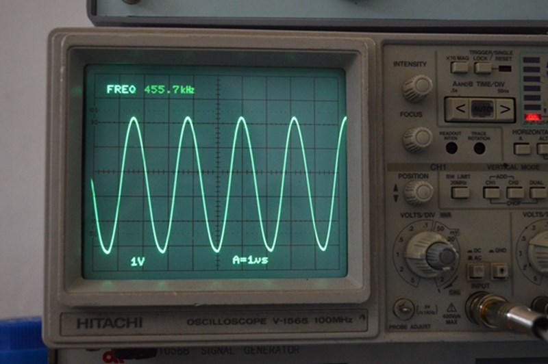
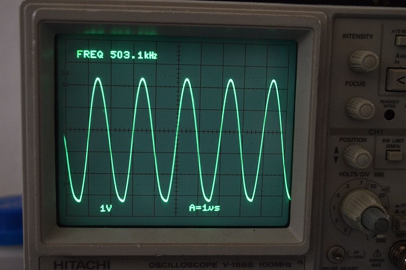
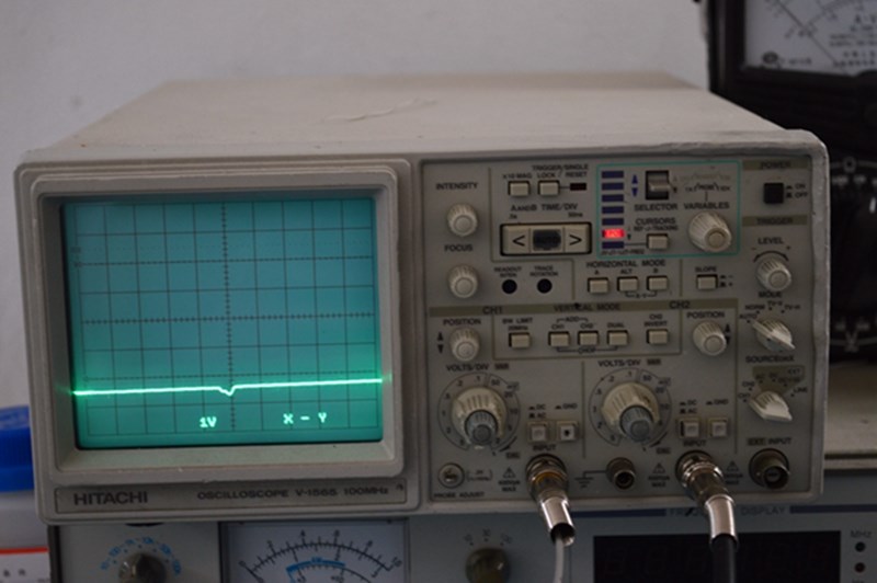
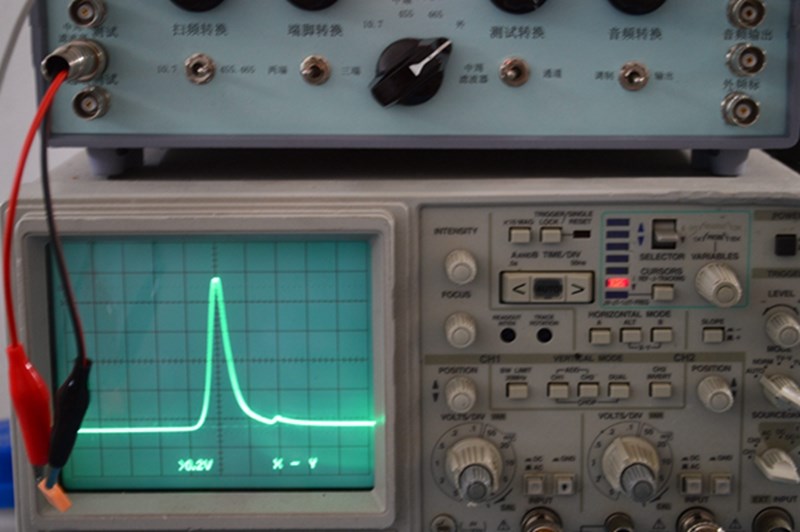
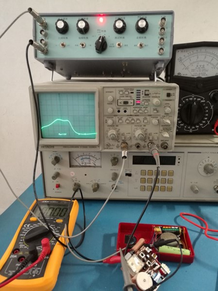
455 waveform
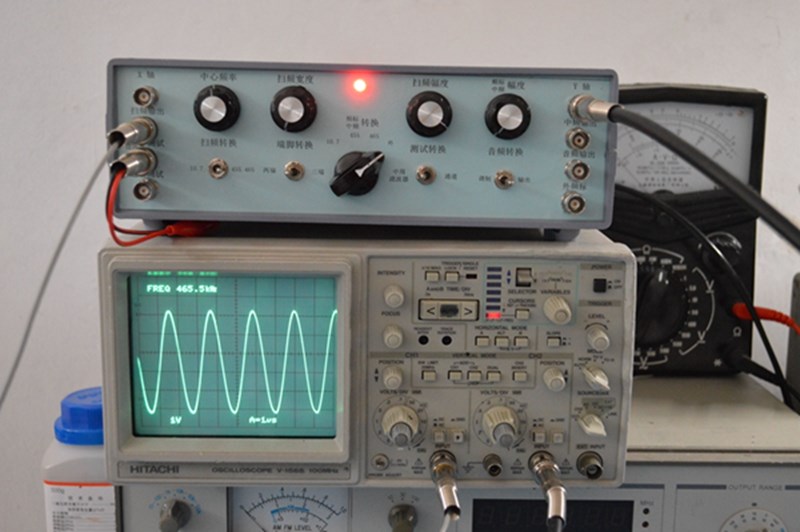
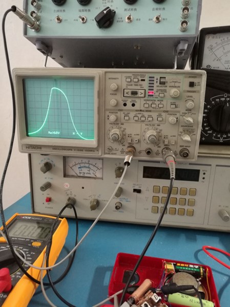
465 waveform
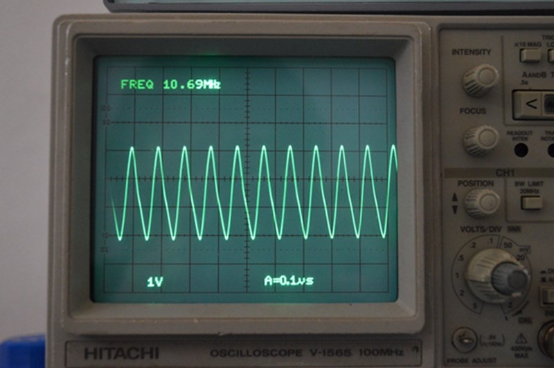
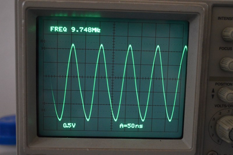
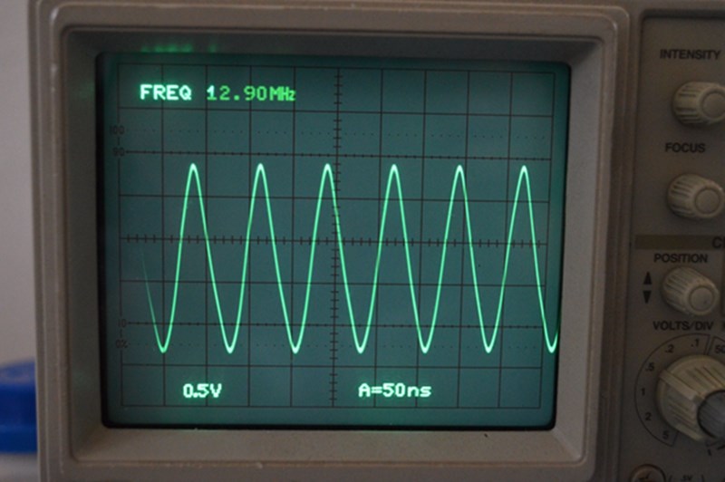
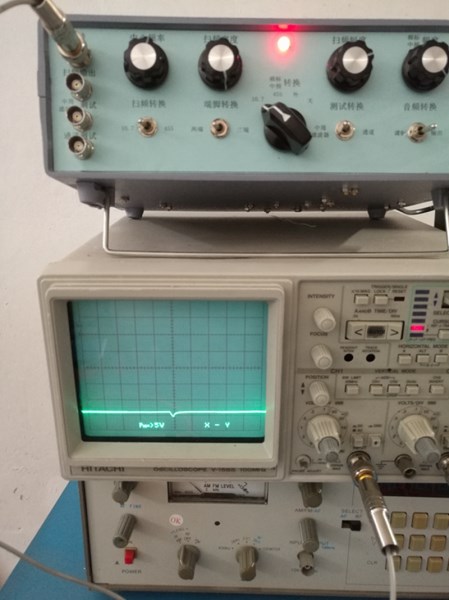
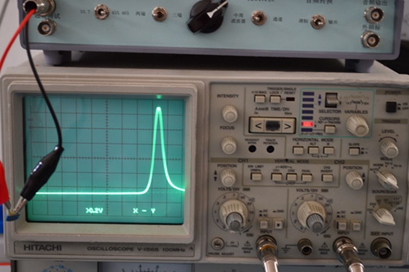
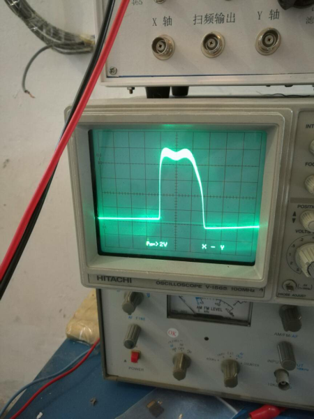
10.7M waveform
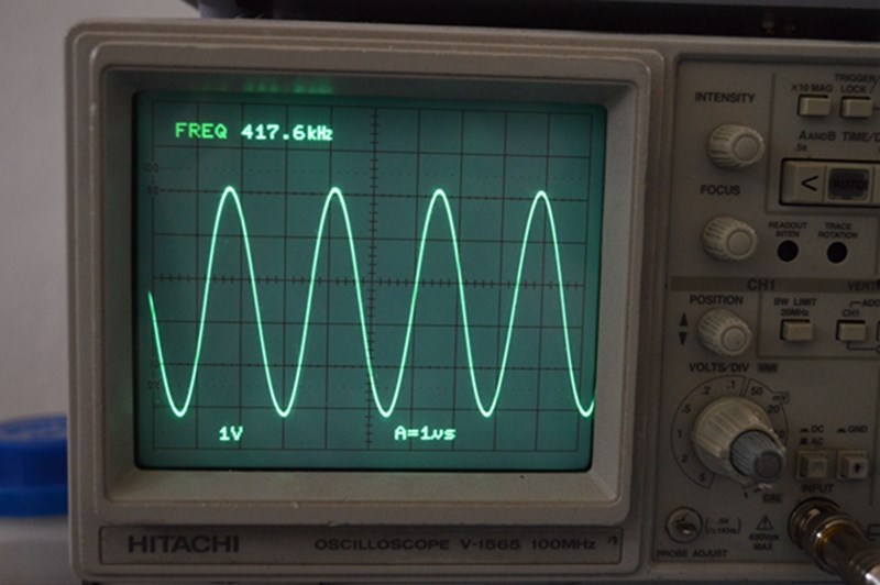
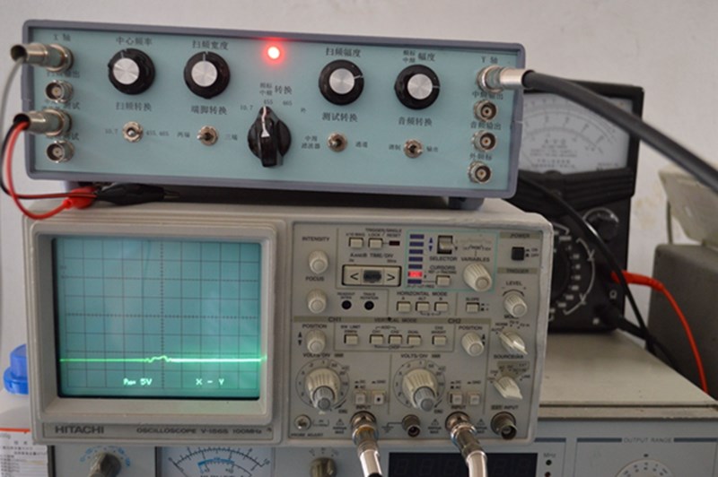
455/465 center frequency range
10.7m center frequency range
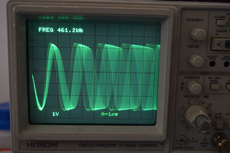
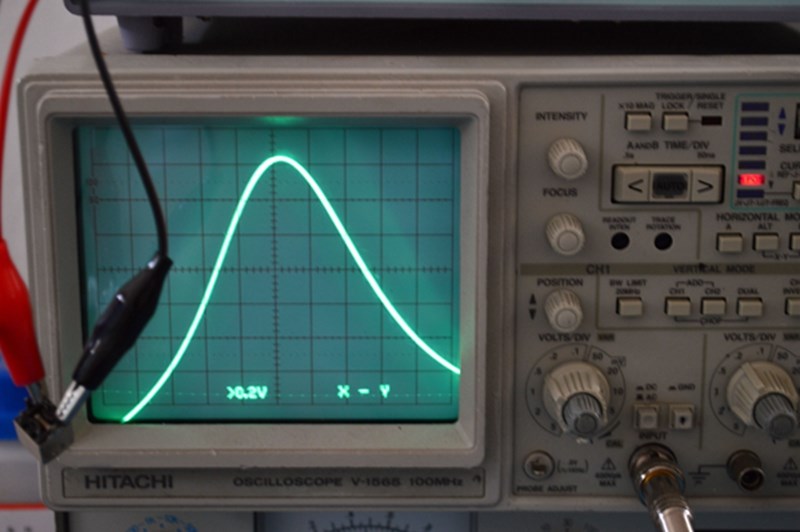
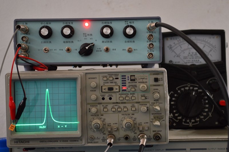
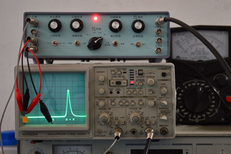
465/455 sweep frequency waveform
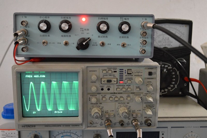
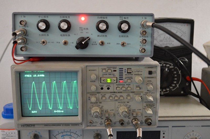
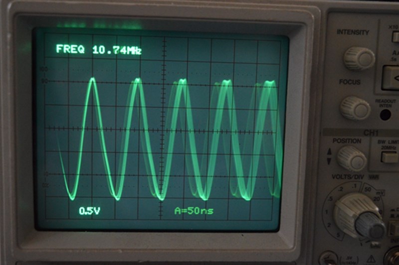
10.7m sweep frequency waveform
465/455 frequency standard
10.7M frequency standard
465 mid-week test
23250.00G-terminal filter test
22750.00G-terminal filter test
465 filter with large error
465 Test of three-terminal filter
10.7M crystal oscillator test
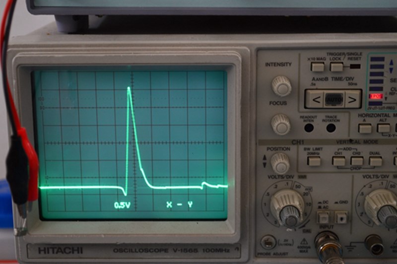
before debugging the small radio
after debugging the small radio
3p5 bimodal waveform after debugging
S curve of FM radio after debugging