Condition:New
Type:Logic ICs
GCAN-201
232/485-CANconverter
UserManual
Document version:V3.05(2017/07/05)
Contents
1Introduction3
1.1Overview3
1.2Propertiesataglance3
2Installation4
2.1ConnecttoPC4
2.2ConnecttoCAN-Bus4
2.3Interfacedefinition4
2.4SystemLED5
3Configurationinstructions7
3.1Readytoconfigure7
3.2Softwareconnection7
3.3Configuretransformationparameters7
3.4Configureserialportparameters8
3.5ConfigureCANparameters9
4Examples11
4.1Transparentconversion11
4.2Transparentconversionwithidentity13
5TechnicalSpecifications14
Salesandservice15
1Introduction
1.1Overview
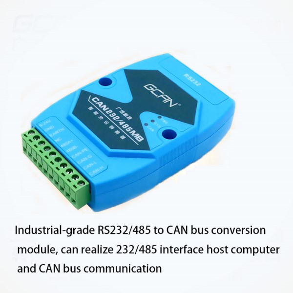
The GCAN-201 converter has integrated one standard CAN-Bus interface, one Serial-Bus interface (RS232 or RS485). GCAN-201 converter can build a connection between Serial-Bus and CAN-Bus. With this converter, equipment that used Serial-Bus can connect to CAN-Bus without changing the hardware structure, this makes multi-Bus interconnection very flexible, and extends the application scope of CAN-Bus.
1.2Properties at aglance
lStandard serial port level, RS232 model or RS485 model can switch by software
lConversiondirectioncanbesetto:CANßàSerial,CANßSerial,CANà
Serial
lSerial Bus baud rate range from 600bps to115200bps
lCAN-Bus supports CAN2.0A and CAN2.0B frame format, conform to ISO/DIS 11898standards
lCAN-Bus baud rates range from 5Kbps to1Mbps
lCAN-Bus interface with electrical isolation
lCAN-Bus isolation module insulation voltage: DC1500V
lPower supply: 9~30V(20mA, 24V DC)
lInstallation method: DIN guiderail
lWorking temperature range from -40 to 85°C
lSize: (L)112mm * (W)70mm *(H)25mm
2Installation
2.1Connect toPC
The converter can be connected directly to a PC using an USB to RS232 cable. If PC have RS232 port, using RS232 directly is also possible.
2.2Connect toCAN-Bus
In practical use, connecting the CAN_H to CAN_H and CAN_L to CAN_L, then communication can be realized.
2.3Interfacedefinition
GCAN-201 converter port definition as shown in figure 2.1 and figure 2.2, using the terminal and the RS232 port, for industrial field application.
Figure 2.1 GCAN-201 RS232 port definition
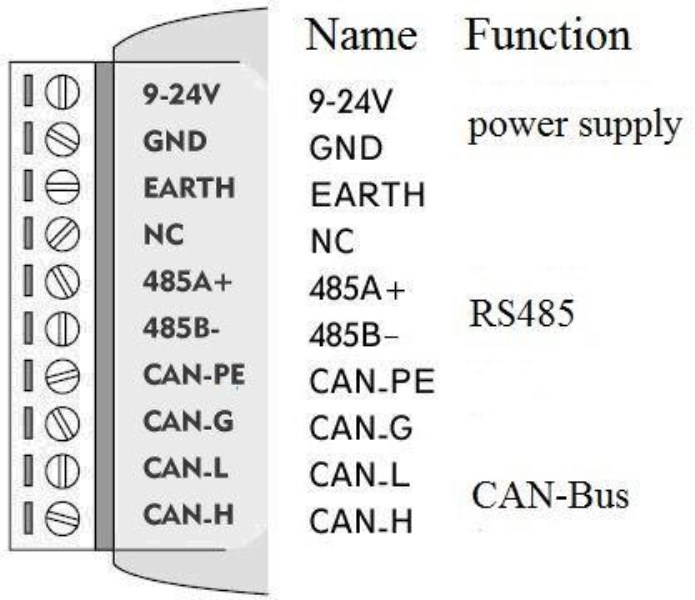
Figure 2.2 GCAN-201 terminal definition
Note: The CAN-Bus network adopts topological structure, only the two furthest terminal need to connect 120Ω terminal resistance between CAN_H and CAN_L. For branch connection, its length should not be more than 3 meters. CAN-Bus nodes connection as shown in figure 2.3.

Figure 2.3 CAN-Bus network
2.4SystemLED
GCAN-201 converter with one PWR indicator, one COM indicator, one CAN indicator to indicate the converter status. More functions are shown in table 2.1.
Indicator
|
State
|
Meaning
|
PWR
|
ON
|
Power supply normal
|
OFF
|
Power supply error
|
COM
|
OFF
|
No data
|
Blinking
|
COM data transmission
|
CAN
|
OFF
|
CAN-Bus no data
|
Red
|
CAN-bus error
|
Blinking
|
CAN-Bus data transmission
|
Table 2.1 GCAN-201 converter LED state
If PWR indicator lights up, it indicates that you plug GCAN-201 converter into an electricity supply, and the system is initialized.
Otherwise, a system power failure or system error has exist.
When Serial-bus data is being transmitted, COM indicator will blinking.
When CAN-bus data is being transmitted, CAN indicator will blinking in green. If CAN error occurs, CAN indicator will turn red.
When COM and CAN indicator blink alternately, it means the adapter is in configuration mode.
3Configurationinstructions
3.1Ready toconfigure
First, power on the converter, then using a thimble click reset button at the side of the DB9 interface module. Module of COM light and CAN light flashing interactively, that module to enter configuration mode. After connecting the module of the RS232 interface and PC, enter the device manager to find the serial port Number.
Note: the serial NO.(COM) can be modified in device manager interface, GCAN-201 can only be configured through the RS232 interface.
3.2Softwareconnection
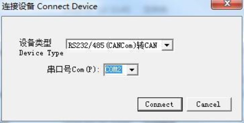
When the GCAN-201 converter enter the configuration mode and in connection with PC via a serial port, open the“RS232CAN-Config”software as shown in figure 3.1.
Figure 3.1 RS232CAN-Config main interface
3.3Configure transformationparameters
Transformation parameters interface as shown in figure 3.2. GCAN-201 supports two kinds of working mode : Transparent conversion and Transparent conversion with identity. GCAN-201 supports three kinds of conversion direction : bidirectionalswitching、CAN→serialport、serialport→CAN. Workingmodeand conversiondirectioncanbemodified in“转换参数”.
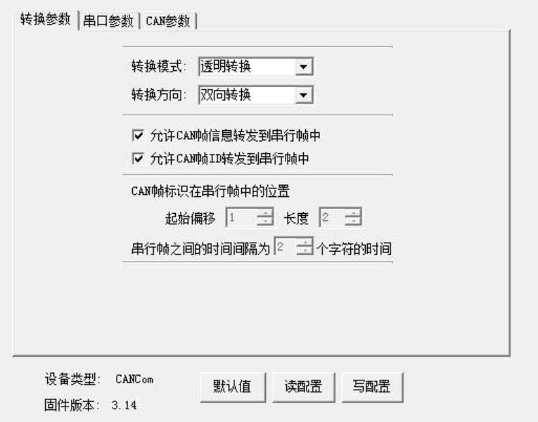
Figure 3.2 Working mode setting
3.3.1Transparentconversion
GCAN-201 will convert the data to the other side immediately if GCAN-201 receives data without adding data and make changes to the data.
“ 允许 CAN 帧信息转发到串行帧中”(Allows CAN frame information to be forwarded to the serial frame)and “允许 CAN 帧标识转发到串行帧中”(Allows CAN frame ID to be forwarded to the serial frame) are only available in Transparent conversion mode.
3.3.2Transparent conversion withidentity
Transparent conversion with identity will convert the data of Serial frame by adding an address into the CAN frame ID . The start position and length of the address can be configured.
3.4Configure serial portparameters
Serial port parameter settings shown as Figure 3.3, GCAN-201 supports serial port baud rate(串口波特率)from 600bps~115200bps, the other parameters do not need to set up.
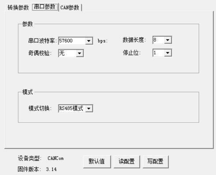
GCAN-201 can switch modes of RS232 or RS485 in serial port parameters(“串口参数”). Click “写配置”(download)after the completion of the configuration, after that you should power-on again.
Figure 3.3 Serial port parameter Settings
3.5Configure CANparameters
CAN parameter setting is shown as Figure3.4. Users can set basic information of CAN-Bus, including CAN baud rate(波特率) and CAN frame type(帧类型).
CAN baud rate supports: 1000K, 500K, 250K, 200K, 125K, 100K, 50K, 20K, 10K, 5K.
CAN frame type supports: standard frame(标准帧), extension frame(扩展帧). CAN frame ID(“发送标识符”)only available in Transparent conversion mode.
GCAN-201 can enable the filter by checking“滤波器使能”. After setting the range and the mode, click add(“添加”).
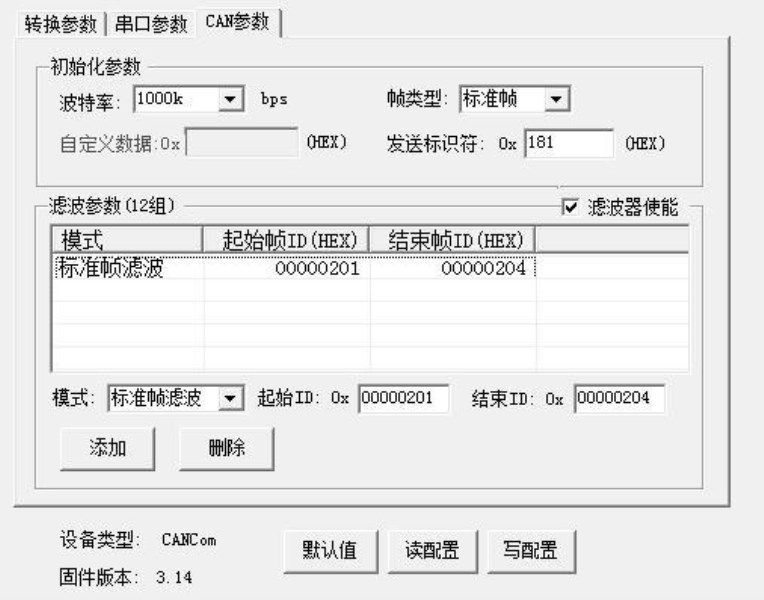
Figure3.4 CAN parameter setting
When the configuration is completed, click “ 写配置 ” to download the module parameters.
When the parameters download is complete, users need to power-on again to effect the new configuration.
4Examples
4.1Transparentconversion
1.Serialport→CAN
GCAN-201 will send the serial data to CAN-Bus immediately if GCAN-201 receive the serial data.
E.g. Serial data 11 22 33 44 55 66 77 88 converts to CAN-Bus. Frame ID is the configuration for“发送标识符” which users have set. Frame data is 11 22 33 44 55 66 77 88.
2.CAN→Serialport
GCAN-201 will send the CAN data to serial port immediately if GCAN-201 receive the CAN data.
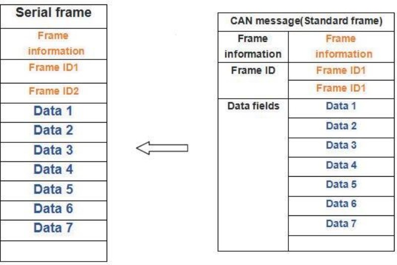
E.g.:Check“允许 CAN 帧信息转发到串行帧中”and“允许 CAN 帧标识转发到串行帧中”which means the CANframe information(帧信息)and the frame ID(帧标识)will display in the serial frame.
CANframeisstandarddataframe.FrameIDis0001.Framedatais1122334455
667788.GCAN-201convertstoSerialport.Serialdatais0800011122334455
66 77 88.
4.2Transparent conversion withidentity
Transparent with identity transformation is the special usage of Transparent conversion.
1.Serialport→CAN
Users can set the start position address and the length of the CAN frame ID in the configuration.
E.g.:If the CAN frame ID starting position address is 1, the length is 2 in the Serial
frame.
Serial frame data is 01 23 33 44 55 66 77 88. GCAN-201 converts to CAN. CAN
frame ID is 123, and frame data is 33 44 55 66 77 88.
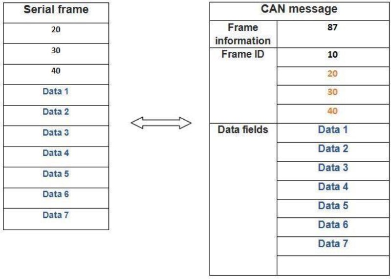
2.CAN→Serialport
E.g.:If the CAN frame ID starting position address is 1, the length is 3 in the Serial frame(Extension frames). Conversion is shown as Figure below.
5 Technical Specifications
Connection
|
Serial interface
|
RS232:DB9;RS485:Terminal blocks
|
CAN interface
|
Terminal blocks
|
Interface characteristics
|
Serial interface
|
Standard RS232/RS485 interface
|
Serial port baud rate
|
600bps~115200bps
|
CAN interface
|
ISO 11898 standard, CAN2.0A/B
|
CAN baud rate
|
1000K, 500K, 250K, 200K, 125K, 100K, 50K,
20K, 10K, 5K
|
Electrical isolation
|
1500V,DC-DC
|
CAN termination resistors
|
None. You can add it between CAN_H and
CAN_L if you need it.
|
Power supply
|
Power supply voltage
|
+9~30V DC
|
The power supply current
|
Maximum 20mA (24V DC)
|
Environmental testing
|
Working temperature
|
-40℃~+85℃
|
Working humidity
|
15%~90%RH, no condensation
|
EMC test
|
EN 55024:2011-09 EN 55022:2011-12
|
Protection grade
|
IP 20
|
The basic information
|
Outline size
|
112mm *70mm *25mm
|
Weight
|
100g
|

