Condition:New
Type:Logic ICs
 The main technical parameters
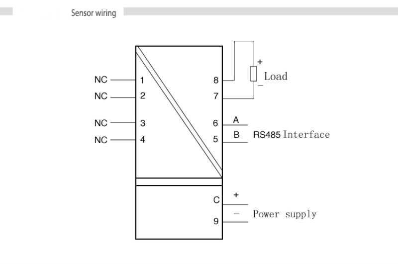
 ● This is a single-channel isolated transmitter. One communication input, one current and voltage output
. The isolation transmitter adopts independent DC power supply mode, power supply-input
-Isolation between outputs.
Standard 35mmDIN rail card installation.
·Power supply
Power supply voltage: 24VDC ± 10%
Current consumption: <60mA (at 24VDC power supply)
Power loss: <1.5W, (when 24VDC power supply)
● Input
Input signal: RS485 communication MODBUS-RTU protocol.
● Output
Output: DC current (voltage) signal
Current output: 4-20mA, 0 ~ 20mA
Voltage output: 0-10V
● Comprehensive main technical parameters
Standard accuracy: ± 0.5% F.S
Temperature drift: ± 0.015% / ℃
Response time: <0.01s (10 ~ 90%)
Stabilization time: ≤0.03s
Influence of power supply change: <± 0.1% allowable voltage range)
Isolation withstand voltage: 2500VDC / min
Insulation resistance:> 100MQ
Communication distance: 1200m
Communication format: 9600, 8, n, 1
Working environment temperature: -10 ~ 50 ℃
Working environment humidity: ≤85RH%
Storage temperature: -30-60 ℃
Dimensions: width 16.6 × height 105 × depth 65 (mm)
Shell material: flame retardant ABS + PC
Dustproof design: Yes
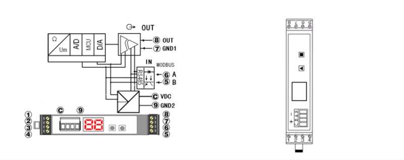
 Operating Instructions:
 The module address is displayed in the normal state of the red digital tube. There are two buttons on the panel. The square button sets the module communication address. Short press the square button and release it. The communication address increases by 1. Keep the square button pressed and the module address will go up Increased to 1 after F7 (module display address is hexadecimal) (module address cannot be repeated, the maximum is 247). The triangular button has no effect on the secondary module.
 Description of Communication Format
 The module uses a fixed communication data format: 9600, 8, N, 1.
The module supports the standard modbusrtu protocol. The module uses the function code 06 (write holding register) and the register address is 00 00 (the register address of most configuration software should be increased by 1, for example, the address in the configuration king is 40001).
Module instruction analysis: Write the analog output value of the module, the command frame sent to the module: 03 06 00 00 13 88 85 7E
The first byte 03 is the module communication address, the second 06 is the function code for outputting the analog value, 0000 is the register address, 13 88 is the output analog value, 85 7E is the crc check, and the low bit is first.
The module returns: 03 06 00 00 13 88 85 7E
The first 03 is the module communication address, the second 06 is the function code for outputting the analog value, 13 88 analog value, and 85 7E is the crc test.
The returned data 13 88 is an integer value, 13 88 is converted to decimal 5000, and then multiplied by a fixed coefficient (see Table 1) is the actual output value. For example, the output signal is 4-20ma, 5000 times the coefficient 0.001 is equal to 5.000ma.

