Condition:New
Type:Logic ICs
Chapter One Product Introduction
One.Overview
MB5TH 5SHT10/11temperature acquisition module can collect 5 channels of Swiss (SENSIRION) SHT10/11temperature and humidity sensor, which has high temperature accuracy and good consistency; the temperature and humidity signal data collected by the module is output through the RS485 interface; the module adopts Modbus -RTU communication, can be adapted to PLC, man-machine screen, DCS and various configuration software, etc.
The module updates the online status of the sensor in real time, and can monitor the online status of the 10external DS18B20sensors in real time through the corresponding register status query.
It can be used for cold storage temperature data collection, vegetable greenhouses, animal breeding, industrial environment monitoring, granary temperature monitoring, egg hatching, medical cold storage and various environmental temperature data collection and control, etc.
two.Features
1.High-speed acquisition of Swiss (SENSIRION) SHT10/11temperature and humidity sensor, good real-time temperature monitoring.
2.Real-time monitoring of the online status of the sensor sensor SHT10/11, which is convenient for users to deal with problems on site and locate fault locations.
3.5Digital tube display, alternately displays the real-time temperature and humidity value of each channel, which is convenient for viewing real-time temperature and humidity on site.
4.Using standard Modbus-RTU protocol, it can be adapted to PLC, man-machine screen, DCS and various configuration software, etc.
5.Communication protection: Isolated RS485 communication, the signal output interface adopts double protection of overvoltage and overcurrent.
6.Power polarity protection.
three.Technical index
project | parameter |
Temperature and humidity signal input | 1. Input channel: 5 channels of temperature and humidity sensor signal acquisition 2. Sensor type: SHT10/11(Swiss SENSIRION) 3. Sampling rate: 1channel is collected every 4mS, and all collection is completed in 20ms. 4. Measuring range: temperature -50~80°C humidity 0-100% (RH) relative humidity 5. Resolution: Temperature 0.1°C Humidity 0.1% (RH) 6. Transmission distance: >= 20 meters |
display | 1.The first green digital tube on the left shows the channel number 2.The four red digital tubes on the right display the temperature value with one decimal point. 3.There are two units on the right to indicate the decimal point, which respectively indicate temperature and humidity |
RS485 Communication output | 1. Communication protocol: MODBUS-RTU 2. Interface type: electrical isolation RS485 communication, the output interface adopts double protection of overvoltage and overcurrent 3. Baud rate: 1200, 2400, 4800, 9600, 19200, 38400, 57600, 115200bps 4. Parity bit: no parity, even parity, odd parity 5. Setting method: module address, baud rate, parity bit can be set by software 6. Communication distance: @9600bps 1200 meters 7.RS485Communication circuit circuit and CPU isolation voltage protection: 1500V |
Module size | 65mm*46mm*28.3mm |
Installation method | Standard DIN rail installation (35mm rail) |
working environment | Temperature: -20 ~ 60°C Humidity: 0~100% (no condensation) |
Power supply | 1. Power supply voltage: 10V~30V wide range power supply, with power polarity protection 2. Power consumption: less than 1.5W |
four.Appearance
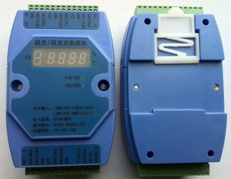
Fives.Module indicator and switch function description
1.POW/SET;Module working status indication
A.Green light on: The module is working in the running state. B. Red light on: The module has configuration parameters that have been written, and need to be powered on again.
2.TXD/RXD:Communication status indication
A.Green light flashes: communication received data B. Red light flashes: module is sending data
C.Steady green light: The communication RS485 lines connected to DATA+ and DATA- are connected reversely or the wiring is disconnected.
3.Reset switch in the upper left corner of the module
A.When the communication parameters (module address, baud rate, check digit) are not known or the communication parameters are set incorrectly, and communication with the module cannot be established, the solution is to reset the communication parameters; we use a paper clip to press and hold the reset switch and do not let go After 5 seconds, the red indicator light of the module [POW/SET] will be on, release the reset switch, the communication parameters have been reset at this time, as long as the power supply of the module is restarted once, the communication parameters of the module have been reset at this time.
B.Communication parameters after reset: address: 1, baud rate: 9600bps, parity: none.
six.Typical application wiring diagram
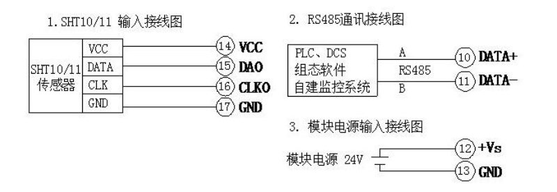
Seven.Terminal definition
Terminal | name | Description |
| Terminal | name | Description |
1 | VCC | SHT10/11Power+ | 26 | NC | air |
2 | DA3 | SHT10/11DATAsignal | 25 | GND | SHT10/11Power ground |
3 | CLK3 | SHT10/11CLKsignal | 24 | CLK2 | SHT10/11CLKsignal |
4 | GND | SHT10/11Power ground | 23 | DA2 | SHT10/11 DATAsignal |
5 | VCC | SHT10/11Power+ | twenty two | VCC | SHT10/11Power+ |
6 | DA4 | SHT10/11 DATAsignal | 21 | GND | SHT10/11Power ground |
7 | CLK4 | SHT10/11 CLKsignal | 20 | CLK1 | SHT10/11 CLKsignal |
8 | GND | SHT10/11Power ground | 19 | DA1 | SHT10/11 DATAsignal |
9 |
|
| 18 | VCC | SHT10/11Power+ |
10 | DATA+ | RS485 ACommunication+ | 17 | GND | SHT10/11Power ground |
11 | DATA- | RS485 Bcommunication- | 16 | CLK0 | SHT10/11 CLKsignal |
12 | +Vs | Power input+ | 15 | DA0 | SHT10/11 DATAsignal |
13 | GND | power input- | 14 | VCC | SHT10/11Power+ |
Eight.Principle block diagram

Chapter twoModbusRegister and communication protocol description
One.MODBUS function code and address range supported by the module
Register type | Address range | function code | Function code description |
Binary input register | 10001-10005 | 0x02H | Read one or more binary input registers |
Input register | 30001-30010 | 0x04H | Read one or more input registers |
Holding register | 40033-40043 40065-40076 40129-40132 | 0x03H | Read one or more holding registers |
0x06H | Write a data to the holding register |
0x10H | Write one or more data to the holding register |
two.Register definition description
1.Binary amountregister(0x02H)
address | parameter | read/write | Minimum | Max | Description |
10001 | DI0 | Read only | 0 | 1 | aisle0SHT10/11online status |
10002 | DI1 | Read only | 0 | 1 | aisle1SHT10/11online status |
10003 | DI2 | Read only | 0 | 1 | aisle2SHT10/11online status |
10004 | DI3 | Read only | 0 | 1 | aisle3SHT10/11online status |
10005 | DI4 | Read only | 0 | 1 | aisle4SHT10/11online status |
2.Input register(Function code: 0x04H)
address | parameter | Read/write | Minimum | Max | Description |
30001 | aisle0SHT10/11Temperature value | Read only | -500 | 800 | Temperature value 0.1/bit |
30002 | aisle0SHT10/11Humidity value | Read only | 0 | 1000 | Humidity value 0.1% (TH)/bit |
30003 | aisle1SHT10/11Temperature value | Read only | -500 | 800 | Temperature value 0.1/bit |
30004 | aisle1SHT10/11Humidity value | Read only | 0 | 1000 | Humidity value 0.1% (TH)/bit |
30005 | aisle2SHT10/11Temperature value | Read only | -500 | 800 | Temperature value 0.1/bit |
30006 | aisle2SHT10/11Humidity value | Read only | 0 | 1000 | Humidity value 0.1% (TH)/bit |
30007 | aisle3SHT10/11Temperature value | Read only | -500 | 800 | Temperature value 0.1/bit |
30008 | aisle3SHT10/11Humidity value | Read only | 0 | 1000 | Humidity value 0.1% (TH)/bit |
30009 | aisle4SHT10/11Temperature value | Read only | -500 | 800 | Temperature value 0.1/bit |
30010 | aisle4SHT10/11Humidity value | Read only | 0 | 1000 | Humidity value 0.1% (TH)/bit |
3.Holding register (function code:0x03H, 0x06H, 0x10H)
address | parameter | Read/write | Minimum | Max | Description |
40065 | Equipment type | Read only | 0 | 256 | 0x0C(MB5TH 5Road temperature and humidity acquisition module) |
40066 | device status | Read only | 0 | 0x0101 | Bit4: Reset button state Bit0: Module reset request flag |
40067 | Module voltage | Read only | 0 | 300 | 0.0-29.9Veachbit 0.1V |
40068 | Module temperature | Read only | 0 | 100 | -20.0-100.0eachbit 0.1 |
40069 | product version | Read only | 0 | 65535 | hardware version(high8Bit) +Software version(low8Bit) |
40070 | Production information | Read only | 0 | 65535 | year(high8Bit) +batch number(low8Bit) |
40071 | Module address | read/write | 1 | 247 | 1(default) |
40072 | Baud rate | read/write | 0 | 7 | 0(1200) 1(2400) 2(4800) 3(9600)default4 (19200) 5 (38400) 6 (57600) 7 (115200) |
40073 | Check Digit | read/write | 0 | 2 | 0(No verification.)default1(Even parity) 2(Odd parity) |
|
|
|
|
|
|
|
|
|
three.Temperature and humidity sampling value (30001-30004) converted to actual data calculation method
1.Calculation instructions
AIInput type | Measurement data range | display resolution | Actual value calculation |
temperature | -5080 | 0.1 | Each number represents 0.1 |
humidity | 0100% | 0.1% | Humidity value 0.1% (TH)/bit |
2.Calculation example
Such as channel 0 (30001) The number read is 623, then the actual temperature of channel 0 is 62.3/10=62.3
Such as channel 0 (30002) The number read is 123, then the actual humidity of channel 0 is 123/10=12.3%
four.Modbus RTUCommunication example
Read5Road temperature and humidity data example (module address:1)
TX: 01 04 00 00 00 0A 70 0D
RX: 01 04 14 00 C9 01 4E 00 CB 01 4A 00 CA 01 47 00 CF 01 43 00 C7 01 4E CF BC
Chapter III Product Configuration
One.Communication settings
1.Default factory communication parameters
project | Register address | Description | Defaults |
address | 40071 | 1(default) | 1 |
Baud rate | 40072 | 0 (1200) 1 (2400) 2 (4800) 3 (9600) 4 (19200) 5 (38400) 6 (57600) 7 (115200) | 3 |
Check Digit | 40073 | 0(No verification.)default1(Even parity) 2(Odd parity) | 0 |
Data bit | --- | Not adjustable | 8Bit |
Stop bit | --- | Not adjustable | 1Bit |
2.Reset communication parameters
1)Why reset the communication parameters:
a)The user has forgotten the communication parameter setting and cannot communicate with the module.
b)The user has set the communication parameter setting by mistake and cannot communicate with the module.
2)How to reset communication parameters
a)Press and hold the touch switch on the right side of the module for more than 5 seconds until the red indicator light of the module [POW/SET] lights up, then release the touch switch that was held down.
b)The communication parameters have been reset to the default values after the module is powered off and on again.
3.Example of setting communication parameters
A.Current communication parameters: address: 1, baud rate: 9600bps, no check digit
B.Communication parameters that need to be set: address: 2, baud rate: 19200bps, no check digit
C.Organize the commands written by using the 0x10 function code to organize the commands.
project | Number of bytes | data |
address | 1 | 0x01 |
function code | 1 | 0x10 |
initial address | 2 | 0x0046 |
Number of registers | 2 | 0x0003 |
Number of bytes | 1 | 0x06 |
Data 1 | 2 | 0x0002 |
Data 2 | 2 | 0x0004 |
Q1: What Is Your Product Warranty?
A: We Guarantee Our Product Is Fit For Its Normal User Purposes And Is Free From Defects In Materials Or Workmanship.
Q2: What Is Your Company Policy On Defective Goods?
A: Our Company Keep Items Quality For A Long Time. If There Are Any Defective Goods Due To
Production Defects Or Transportation Problem, Please Contact Us. Our Customer Service Team Will Provide Immediate Response To
Complaints. We Will Try Our Best To Give You A Good Resolve Way.
Q3: What Is Your MOQ (minimum Order Quantity)?
A: Generally Our Moq Is No Limited. Please Have More Discussion With Us If Your Combination Of Models Is Complicated.
Q4:how About Getting Samples From You?
A: We Will Send You The Samples After We Receive The Payment For Samples. The Buyer Shall Afford The Shipping Cost. Please Have A
Confirm With Us Which Shipping Way Do You Want.
Q5:about The Shipment: What Type Of Shipment Will You Use?
A: We Usually Ship The Products By Express(delivery It To Your Door) Or By Air Freight To Your Nearest Airport, Shipping Days:3-7
Working Days Depend On Destination;if The Order Quantity Is Large, We May Ship By Sea Container And The Best Ship Way Is By Sea,
Shipping Days: Over 20 Working Days Depend On Destination Port.
Q6:what Packing Do You Use?
A: Neutral Package With Airbag Or Customized Package.
Q7:how Much Are The Shipping Cost?
A:shipping Cost Is Charged By The Package's Weight And Related To The Shipping Methods You Choose And Your Destination.
Q8:how To Order?
Step1.Click (Add to Cart) Buy Directly On The Product Page, Or Add To Shopping Cart And Settle Together, Pay With Paypal,
Need your information, such as full name,country, city, detail address, post code, tax number ...
Step2. We Will Delivery by EMS POST, FedEx or DHL Within
3-5 Working Days After Payment Confirmed.
Setp3. Confirm Us Receipt of Products.