Condition:New
Type:Logic ICs
Place of Power accuracy:10%
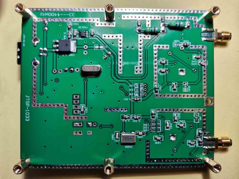
Model:JTGP-1033
bandwidth:999MHz
Applicable scenario:Portable
Rated voltage:5V
Rated current:0.4A
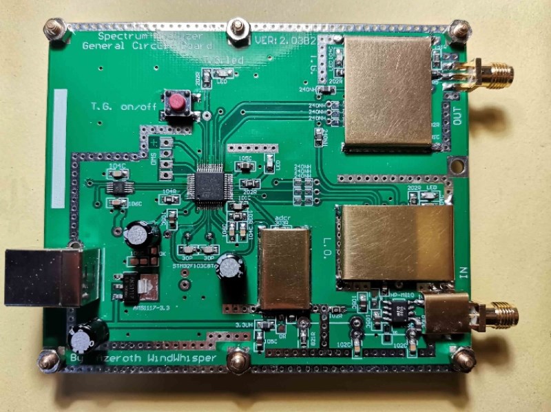
Sweep frequencysimple spectrum D6 V2.03B2 version handmade small production No. 3
properties: RF frequency domain analysis tool
Interface:USB
Electricity:USB
standby current: ≤90mA
frequency sweep current: ≤ 350mA
sweep bandwidth:35mHz---3000mHz
turn on the output bandwidth of the tracking source from 35mhz to 3000mhz
sweep frequency step: ≥35~68.75mHz/125Hz,68.75~137.5mHz/250Hz,137.5~275mHz/500Hz,275~550mHz/1kHz
550~1100mHz/2kHz, 1100~2200mHz/4kHz, 2200~4400mHz/8kHz
sweep speed: ≥800spot/second
dynamic logarithmic ratio of sweep frequency:>50dB
point frequency or sweep frequency output power: ≈-3dBm
input Detection: ≤10dbm
background: ≈-50dBm
computer-side software:NWT4.11.09version
the operating system of the computer:WinXP,win732,win764,win1032
purpose: to measure the frequency and make a simple amplitude-frequency characteristic analysis on the transmission network.
Applicable: radio enthusiasts and young students
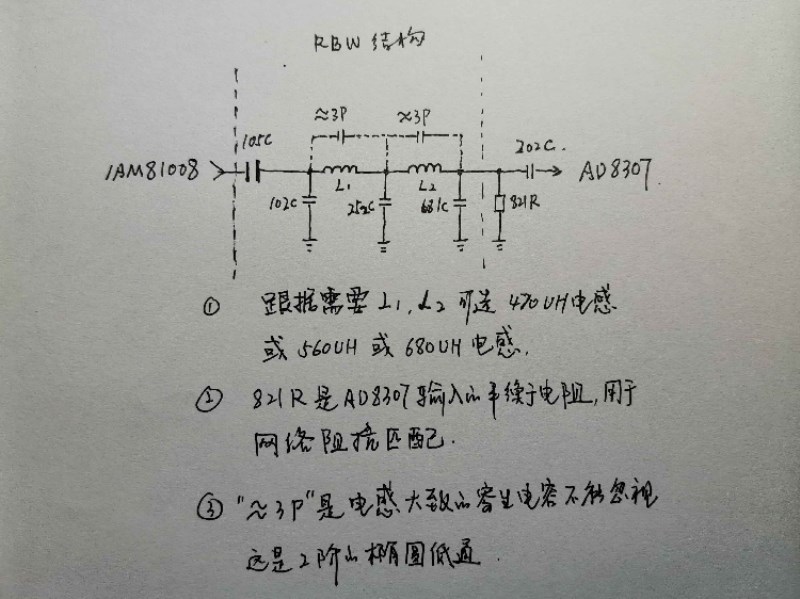
core components: stm32f103c8t6 single chip microcomputer.The adf4351 output is a rectangular wave, and the amplitude changes to the trigger level.IAM81008, mixer chip, uses domestic ps3120 as its power,IAM81008it is a wearing part, easy to break.ad8307, power logarithmic detector。
ch340e, domestic usb to ttl chip,ch340e is highly cost-effective.
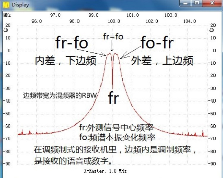
Working Principle and concept: differential frequency scanning, low pass (RBW)120K or200khz。
similarly:
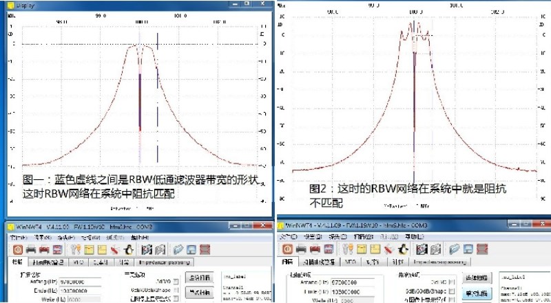
for general applications, the fluctuation of the passband part of the band connection is within 3dB.
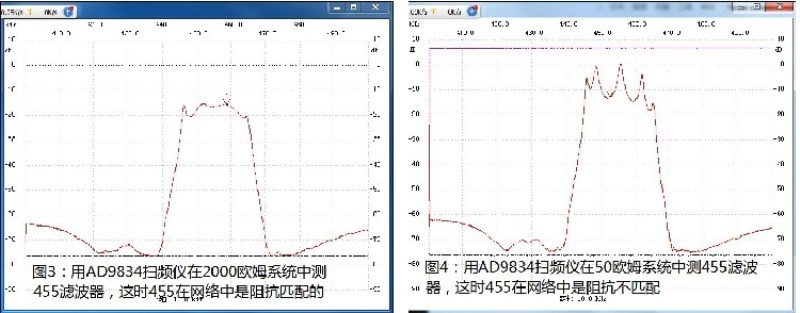
Whether the impedance of the network needs to be matched in the system is determined according to the actual application, not necessarily matched.
These are all frequently asked questions.
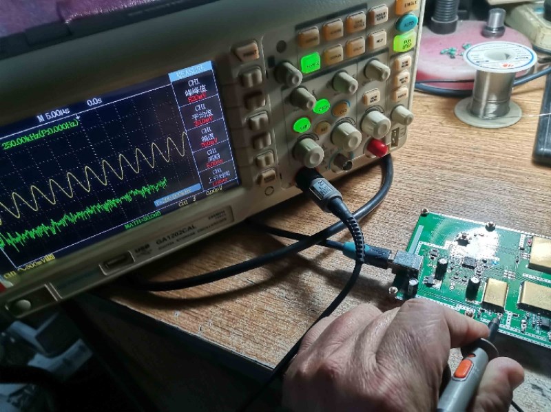
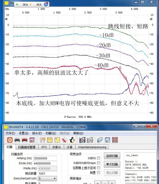
Use jumper short-circuit transmission and input detection port to sweep the frequency and use oscilloscope to observe RBW output, which should be the point frequency of differential frequency (200khz).
Fu Liye transformation, it can be seen that the fundamental wave of the square wave is a sine wave of mathematical significance, and this 200kHz difference frequency is the difference frequency of the fundamental wave output by two oscillators. Other fundamental wave and frequency multiplication, frequency multiplication and frequency multiplication generate differential frequency (alternating and intermodulation) should be filtered out by RBW.
According to the product and difference formula of the (mixing) triangle, the amplitude-frequency change of the measured network between the input and input detection ports is the amplitude change of the 200kHz difference frequency.
Above:
this version originated from an improved copy of D6 sent to me by a radio enthusiast in Shenzhen by a French radio enthusiast studio. I personally think it is necessary to make this new version.
"Ame ?07 liorations sur le d'd6» par Jean Claude F1AIA_Dans mon atelier - David F4HTQ.pdf" online translation"fromGive Way·claude·F1AIAYes"D6"improvement-DavidF4HTQstudio"
I also uploaded this PDF file to Baidu Internet disk shared folder<203B2>Inside.
next, test the new version with the external and self-made attenuation parts.
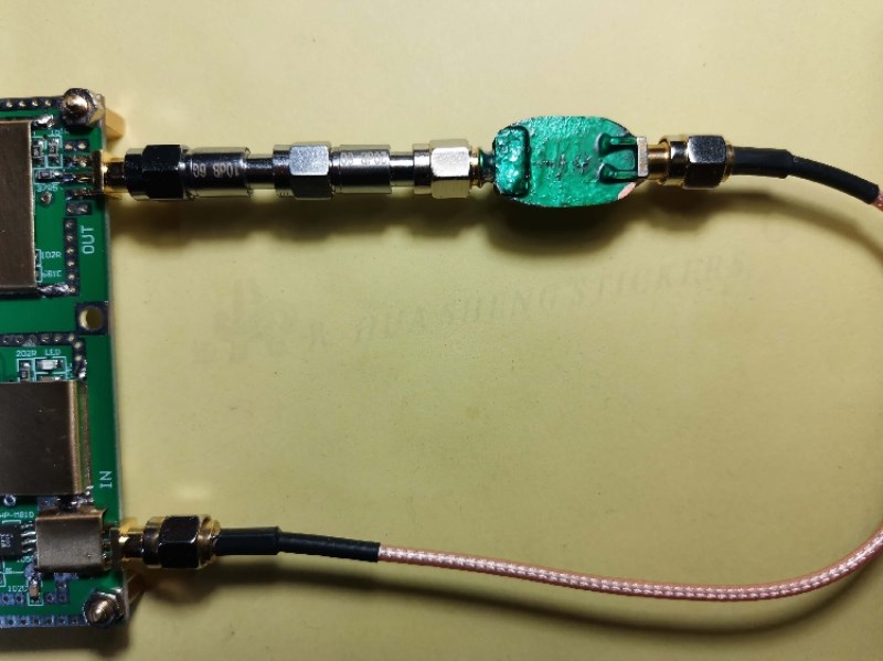
In the new version, 6dB and 3dB attenuation have been added inside the input and output, which is equivalent to 10 dB attenuation in the test loop. The nonlinear attenuation area is removed.
The main change is the one above, the others including the bottom layer of the single chip microcomputer and the V2.03B board are the same,
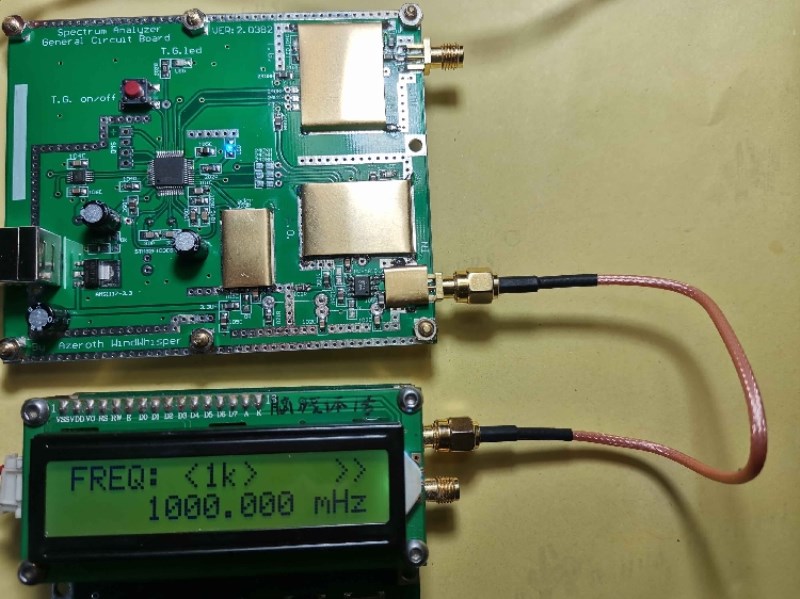
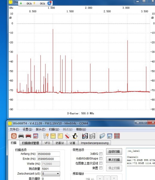
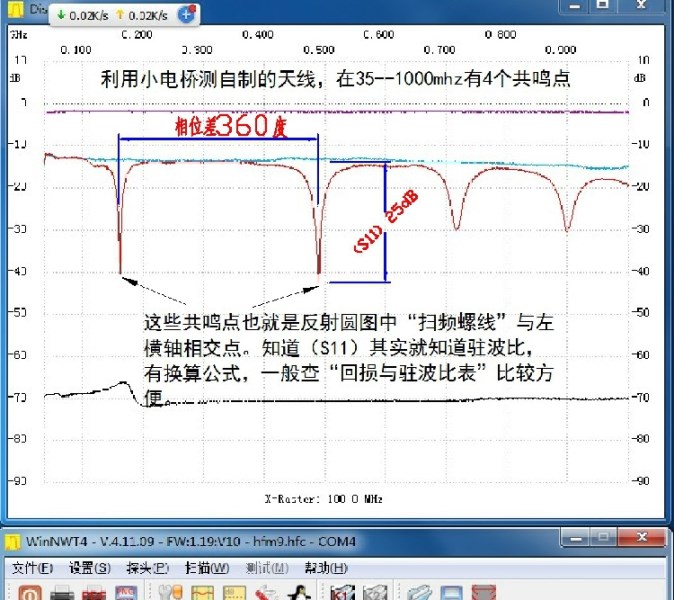
measuring antenna with self-made small Bridge
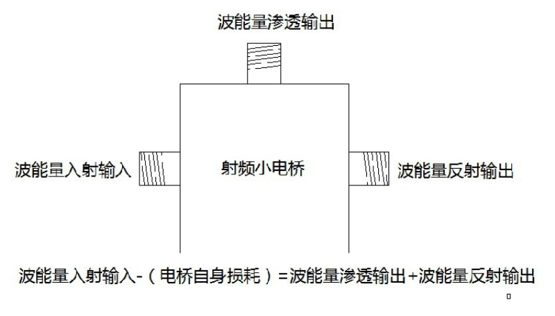
in short, the transmission of energy should be conserved in this process.
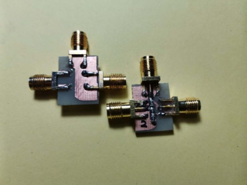
The radio frequency small bridge made during the Spring Festival this year, as an attachment, the manufacture of the small bridge, check our "radio frequency small Bridge".
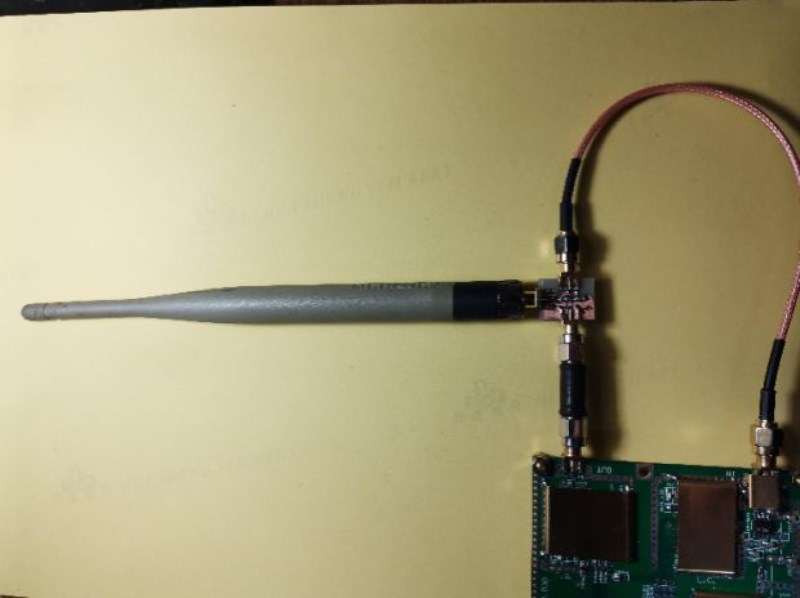
Four harmonic points of the antenna can be seen in the bandwidth of 35-1000MHz. If anyone has a vector division, it should be seen in the reflection circle that the sweep frequency spiral will intersect with the left horizontal axis (inductance dividing line) 4 times within 1000MHz.
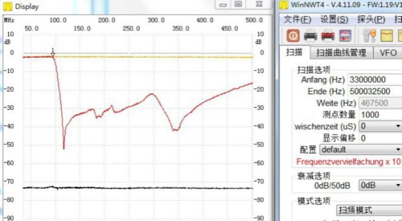
Low-pass filter with measuring bandwidth of 90MHz
accessories are also self-made small bridge, 2 SMA 20cm jumper and USB cable:
Main board*1
SMA 20cm*2
High quality USB cable*1


