Condition:New
Type:Logic ICs
contact form:Conversion type
Model description(new and old customers must see):
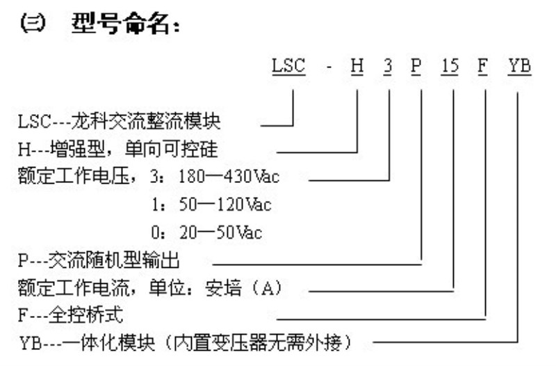
LSC-H3P50FYBFor 220V load /380V load generic typeReCOMmended use). Whether you are a single phase 220VAC input or two-phase 380VAC input can be used to make you type.
The latest upgrade: This product has been used in the United States TI's power management technology chip, the power supply voltage can be in the 180V-430Vac of the extremely wide range of normal work, and has a high reliability.
If the first time you use this product, please Contact with the shopkeeper, shopkeeper will give you the relevant suggestions.

An overview
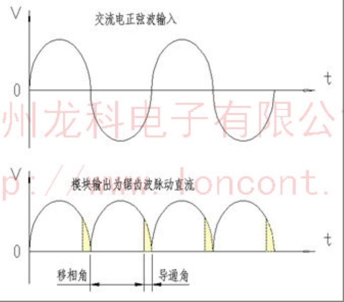
1,LSC-Series integrated single phase rectifier voltage regulator module.Solid-State Commuter LonContInternal set single phase shift trigger circuit, four way Controlled silicon COMposed of a full Control bridge, fourRCRC absorption circuit and a power circuit is equal to one, in the automatic or manual adjustment of the input Control, produce change the conducting angle of trigger pulse signal to Control the internal SCRs, realize AC directly converted into amplitude stepless adjustable DC voltage ripple, load voltage from0VFull range adjustment to the full voltage of the power grid. Module is typically used in a variety of power supply, voltage regulator, DC motor, excitation, welding, electroplating, charging, etc..
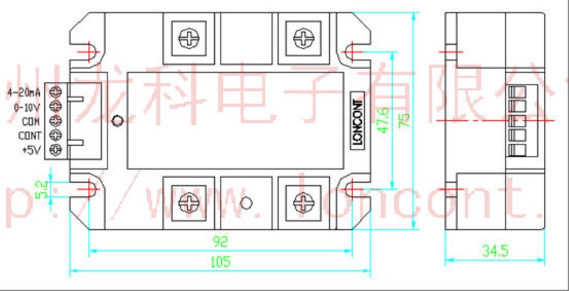
2,0-5Vdc,0-10Vdc,4-20mACompatible input automatic Control mode, can also be used to manually Control the output voltage from the0VTo the maximum linear adjustable. The input range is wide, the output regulation precision is high, and the anti-interference ability is strong.
3Module built-in power supply circuit. No external synchronous transformer, no external DC power supply.
4Module useSMTTechnologyDCBCeramic substrate, small size, less external wiring, stable performance, easy to use, high reliability.
5Module hasLEDPower indication and output regulation indication.
6Between, the input Control terminal and the input terminal of switch power and between the high voltage main loop and full isolation design, insulation dielectric withstanding voltage greater than2000 Vac.
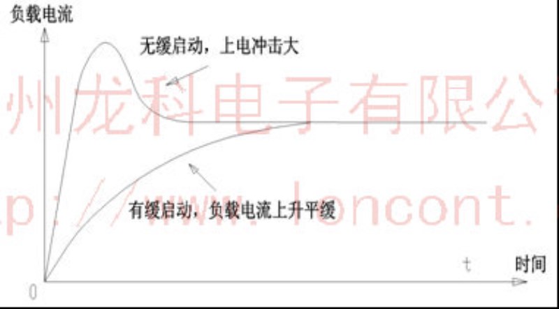
7The module has the function of slow start up function, which can effectively reduce the instantaneous impact current when the load is electrified.
Two module load output current levels and models are as follows:
Electric current
15A
35A
50A
70A
90A
120A
150A
Model
LSC-H3P15FYB
-H3P35FYB
-H3P50FYB
-H3P70FYB
-H3P90FYB
-H3P120FYB
-H3P150FYB


Instructions
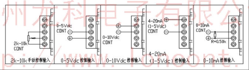
1Unique fully compatible input Control mode,0-5Vdc,0-10Vdc,4-20mA,1-5Vdc,0-10mAAnd other automatic methods are able to adapt, do not need special custom, can also be used to manually Control the potentiometer. The input range is wide, the output regulation precision is high, and the anti-interference ability is strong.
Manual Control of the potentiometer: according to the icon, the middle end of the potentiometer is connected to the modulecontThe two ends of the potentiometer are respectively connected with the module.comEnd and+5VEnd.+5VVoltage by the module itself, without the need for external supply, with only hand control potentiometer with and without it, the selected resistance value of the potentiometer in2-10KInter. When the control sidecontfrom0-5VdcWhen changing the voltage from the DC load0V to the maximum linear adjustable,contThe higher the terminal voltage, the greater the output of the module.
2,0-5VdcControl mode: according to the icon, can be accepted0-5VdcAnalog signal, control input positive polecontNegative electrodecomInternal modulecontEnd relativecomThe input impedance is greater than30KOmega. When the control sidecontfrom0-5VdcWhen changing the voltage from the DC load0V to the maximum linear adjustable, whichcontstay0-0.7VdcWhen the left and right are all closed area, the output of the whole circuit is reliable;contstay0.7Vdc-4.3VdcLeft and right for the adjustable region, that is, with the increase of the control voltage, phase shift angle180To the degree0The lead angle is increased, and the voltage on the load is increased from the angle of the load.0V increase to maximum;contstay4.3Vdc-5VdcAbout when the full opening of the region, the voltage on the load for the maximum value (equivalent to the power grid voltage direct bridge rectifier).
3,0-10VdcControl mode: according to the icon, can be accepted0-10VdcAnalog signal, internal module0-10VdcEnd relativecomThe input impedance is greater than15KOmega.
4,4-20mAControl mode: according to the icon, can be accepted4-20mAAnalog signal, internal module4-20mAEnd relativecomThe input impedance of the250Omega. When to4-20mAControl input,4-5mAWhen the left and right are all closed area, the output of the whole circuit is reliable;5-19mALeft and right for the adjustable region, that is, with the increase of the control current, the phase shift angle180To the degree0The voltage from the load is linearly decreased.0V increase to maximum;19-20mALeft and right for the full opening of the region, the largest output.
5,0-10mAControl mode: according to the graphic, this method should be used in the modulecontWith the end ofcomEnd to end500Omega,1/2WResistance, when input0mAtimecontintention0VdcWhen input10mAtimecontintention5Vdc.
2Function end relativecomEnd must be positive,comThe end of the negative electrode, such as the polarity of the module is connected to the main circuit output terminal may be out of control.
3, the control characteristics of the end of each function module are positive characteristic, control, and the higher the voltage, higher output voltage of the module of high voltage main loop.
4At some point, it is better to use an input control mode, if two or more ways to use the same time, it is generally a strong input signal a major role. The module can be used both manually and automatically, such as automatically connected to the4-20mAHand in hand0-5VFunction switch can be performed by a double throw switch.
5, module power function of slow start up. When the output end and the General Assembly electrolytic capacitor filter, is gradually rising due to the voltage across the capacitor, the capacitor charging is slow, so as not to cause modules over-current damage.
6If silicon controlled silicon in the module is in a small conduction angle (that is, the main circuit input voltage is very high, the output voltage is very low) for a long time to output a larger current, may cause the module serious fever.
The main circuit power output application circuit wiring:
1. The AC input, the output DC to DC positive negative output.
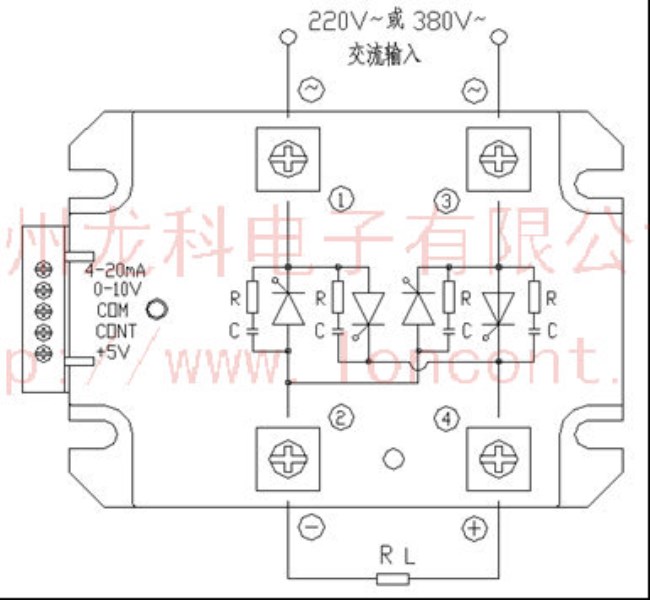
220Vacor380VacAC power supply rectifier application circuit

- Resistance load, the choice of voltage regulator module of the current level should be greater than or equal to3Load current rating.
- When the load is AC motor, the current level of the voltage regulator module must be greater than or equal to5-6Times the rated current of the motor.
- meetThe current rating of the voltage regulator module should be greater than or equal to the load of the electromagnet and the inductance coil.4Load current rating.
- meetWhen the capacitive load is, the current level of the voltage regulator module must be greater than5Load current rating.
- Transformer is greater than or equal to5Transformer primary rated current, special inductive, capacitive load should be based on the actual situation still need to enlarge the voltage regulator module of the current margin.
High current voltage regulator module with optional optional radiator, radiator specific specifications please contact the shopkeeper.

Does not recommend the controllable silicon in the modules in the smaller guide angles (i.e. main circuit input voltage is high, and the output voltage is very low) under long time large output current, if the actual load voltage lower, can be the first to use transformer will reduce voltage and then module rectifier as the pressure.
At this time can chooseLSC-H1PxxFYBorLSC-H0PxxFYBLow voltage series.

