Condition:New
Type:Logic ICs
Single-phase thyristor trigger, single-phase thyristor phase shift trigger board, single-phase thyristor trigger module, our company is complete, please choose the right model according to your application:
For applications where input single-phase AC is used and the output is adjustable AC, the following models are available:
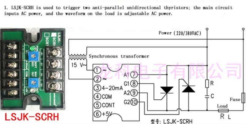
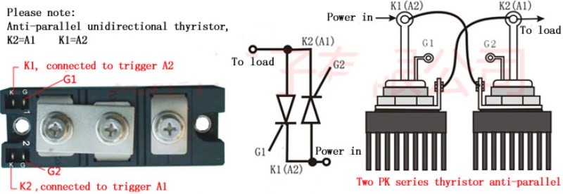
1. One-way thyristor enhanced voltage regulator type phase shifting trigger, LSJK-SCRH (for triggering two anti-parallel unidirectional thyristors)
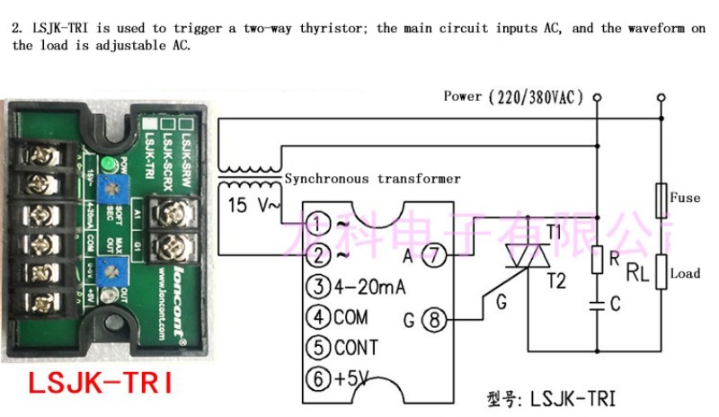
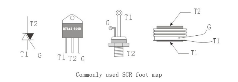
2. Bidirectional thyristor voltage regulator type phase shifting trigger, LSJK-TRI (for triggering a two-way thyristor)
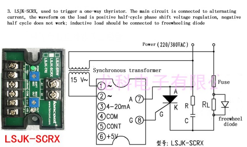
3. One-way thyristor half-wave voltage-regulating phase shifting trigger, LSJK-SCRX (used to trigger a one-way thyristor)
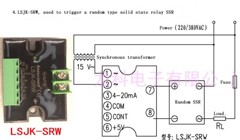
4. Single-phase random type solid state relay phase shifting trigger, LSJK-SRW (used to trigger a random type solid state relay SSR)
You can also choose the integrated voltage regulator module produced by our company, that is, the module with the trigger circuit and the thyristor combined into one, the wiring is more convenient! Learn more:
Https://www.aliexpress.com/item/4000058688205.html
For applications where input single-phase AC is used and the output is adjustable DC, the following models are available:
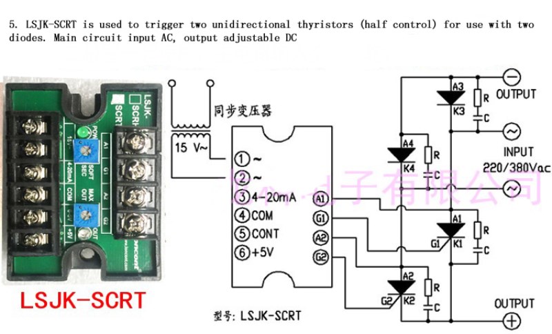
5. One-way thyristor half-controlled bridge rectifier phase shifting trigger, LSJK-SCRT (half control, used to trigger two unidirectional thyristors and two diodes)
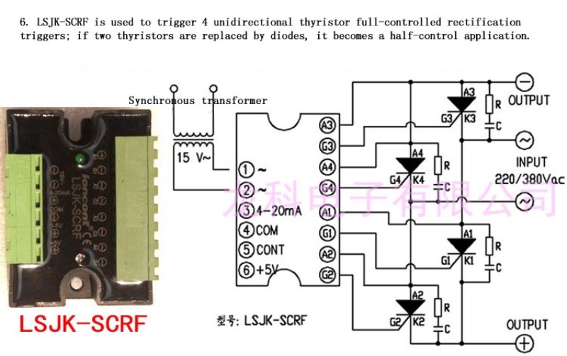
6. One-way thyristor full-control bridge rectifier type phase shifting trigger, LSJK-SCRF (full control, used to trigger four one-way thyristors)
LSJK series single-phase thyristor trigger is a phase-shifting thyristor trigger circuit. Its core components are high-performance, high-reliability AAA-level thyristor trigger ASICs. The output trigger pulse has very high symmetry and stability, and does not change with the ambient temperature. It is not necessary to adjust the pulse symmetry and limit in use. On-site debugging generally does not require an oscilloscope to complete. It can be widely used in various fields of industrial voltage and current regulation, suitable for resistive loads, inductive loads, transformer primary side and various rectifiers.
This product triggers thyristors mainly for the following industrial fields:
A electric furnace industry: annealing furnace, drying furnace, quenching furnace, sintering furnace, furnace, tunnel furnace, furnace, box type electric furnace, well type electric furnace, melting electric furnace, rolling electric furnace, vacuum electric furnace, trolley electric furnace, quenching electric furnace, aging Electric furnace, cover type electric furnace, atmosphere electric furnace, oven test electric furnace, heat treatment, resistance furnace, vacuum furnace, mesh belt furnace, high temperature furnace, kiln, electric furnace
B mechanical equipment: packaging machinery, vacuum coating, injection molding machinery, heat shrinking machinery, extrusion machinery, food machinery, tempering equipment, plastic processing, infrared heating
C glass industry: glass fiber, glass forming, glass melting, glass printing, float glass production line, annealing tank
D automotive industry: spray drying, thermoforming
E energy-saving lighting: tunnel lighting, street lighting, photographic lighting, stage lighting
F chemical industry: distillation evaporation, preheating system, pipeline heating, petrochemical, temperature compensation
Product feater:
The principle of the phase shifting trigger is based on the size of the control voltage CONT (the control signal is usually 0-5V, 0-10V, 4-20mA, 1-5V, 0-10mA, etc.), and the output is doubled in synchronization with the grid voltage. Wide pulse with a phase shift angle a of the grid frequency varying from 180° to 0° to drive a unidirectional or triac, so that the voltage across the AC load is linearly adjustable from 0 volts to full voltage, thus moving The purpose of phase regulation. The trigger includes a synchronous phase detection circuit, a sawtooth wave forming circuit, an input control adjustment circuit, a reference circuit, a phase shift comparison circuit, a drive trigger output circuit, and a regulated power supply that provides operation of these circuits. The product is ultra-small and ultra-thin design, SMT patch technology. It can be flexibly combined with one-way and two-way thyristors for half-wave and full-wave AC voltage regulation. The potentiometer can be manually controlled or the voltage signal and current signal can be automatically controlled. The trigger uses a single wide pulse strong trigger to accommodate inductive or resistive loads.
The relationship between the phase shift trigger control voltage Ucont and the output pulse duty ratio Y is as follows
(Take 0-5VDC control method as an example):
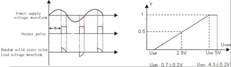
The control voltage is in the OFF region at 0V-Uoff, and the output of the main circuit voltage is reliably turned off.
The control voltage is a basic linear region in Uoff-Uon. As the control voltage signal increases, the voltage on the main circuit load also increases.
When the control voltage is Uon - 5V, it is the all-conducting area, and the voltage on the load is the grid voltage.
Technical parameter:
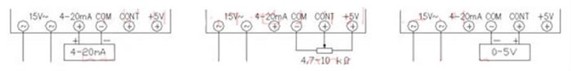
Control method: as shown above, select the desired way to connect;
Compatible with 4-20mA signal control, 0-5VDC signal control, potentiometer manual control, multi-function three-in-one.
5V is used for potentiometers, not for letting you give it 5V power. If you do not use potentiometer control, ignore the 5V terminal
1, 2 feet connected to the secondary winding of the synchronous transformer, the voltage is 15±3Vac, supply the power and synchronous reference of the phase shifting trigger; 3 feet are the pulse phase shifting control end, when the 3 pin input has 4-20mA relative to the 4 pin When the current signal is output, the output terminal outputs a wide pulse of a phase shift which produces 180° to 0°;
The 4 pin (COM end) is internal, when the phase shift flip-flop is automatically controlled by an external circuit, the 4 pin is connected to the ground of the external circuit;
The 5 pin (CONT end) is the pulse phase shift control terminal. When the 5 pin input has a 0-5Vdc voltage signal relative to the 4 pin, the output end generates a 180° to 0° phase shiftable wide pulse;
The 6-pin (+5V terminal) is the +5V voltage terminal generated inside the phase-shifting trigger. When the 654-pin external potentiometer is manually controlled, the 6-pin provides power. When the external circuit provides the control signal, the 6-pin is not used.
3. Other technical parameters of the phase shifting trigger:
The voltage of the secondary winding of the external transformer of the a.12 pin is required to be within 15±3VAC. The required current is about 30mA, and the power is 1W or 2W.
b. The 6-pin +5V voltage signal is used for power supply when the manual potentiometer is controlled. It is not used for other purposes. The selected potentiometer value is generally between 4.7KΩ and 10KΩ.
C.3 pin control terminal current changes in the range of 4-20mA, 34-pin input impedance 250Ω.
The voltage of the d.5 pin control terminal is changed within the range of 0-5V, and the input impedance of the 54 pin is greater than 15KΩ.
e. If other control signals such as 0-10V are required, please specify when ordering.
f. Opto-isolation between the control part of the phase shifting trigger and the output triggering end.
g. Trigger has LED power indication (green) and LED output adjustment indicator (white hair red).
When the synchronous transformer has a voltage input, the green light is on; when the trigger has an output, the red light is on, and the larger the output, the brighter the red light.
Wiring diagram:
The function of RC resistance-capacitance absorption circuit is to limit the voltage rise rate of the circuit to be too large and ensure the safe operation of thyristors. The SCR should be connected with the RC absorption circuit according to the following circuit diagrams, in which R chooses 30-100, the power is greater than or equal to 3W; C chooses 0.1 f-1.0 f, 250 VAC or more than 400VAC. (RC resistance and capacitance absorption information can also be consulted with thyristor manufacturers)
The MAX OUT knob is used to adjust the upper limit limiting the output voltage. By default, no restriction is imposed, i.e., full voltage can be output. The upper limit of output voltage can be limited by adjusting the knob gently. For example, when adjusted to a certain position, even given a large signal value, the output voltage is only 70%, and the upper limit of output voltage is limited to 70%.
SOFT SEC knob is used to adjust slow start time. By default, there is no slow start, that is, the output changes synchronously with the signal. The time of slow start can be adjusted by adjusting the knob gently. For example, the original given signal makes the output voltage 50% instantaneous. After adjusting the knob, the output voltage takes 1.5 seconds from 0 to 50%, and the current slow start time is 1.5 seconds.
Do not adjust these two functions for the first time. After the debugging circuit is normal, try again.
Tips for using:
There are two lights on the trigger, one is the green light and the other is the red light.
The green light represents the synchronous signal input, that is, the 15V secondary of the synchronous transformer has been supplied to the trigger. If the green light is not on, please check whether the connection of the synchronous transformer is normal.
The red light represents the input of control signal, that is, the control of 0-5V/4-20mA/potentiometer plays a role, and the stronger the signal, the stronger the red light brightness. If the red light is not on, please check the input of the control signal. When the red light is on, there should be voltage on the load. If there is no voltage on the load, please check the connection of thyristor.
Please note that when using any trigger, it is necessary to connect the SCR to the load during debugging, and the SCR can not be debugged without load. It is possible to use incandescent lamp to carry out light-load experiment under thyristor load.