Condition:New
Type:Logic ICs
Color classification:Active input dry contact input
Chapter 1 product introduction
One Summary
MB16DI16RO 16The circuit switch input acquisition module and the 16-way relay output module can collect 16 trunk or wet node signals (active or passive input); as dry contact input or sensor input (NPN or PNP), jumper common positive or negative input can be set; as active input, polarity automatic conversion does not need jumper switching; The 6-way relay can be controlled by MODBUS bus. The module adopts Modbus-RTU communication, and can directly adapt to PLC, DCS and various domestic configuration software.
Switch input and relay input, power input, RS485 communication electrical signals are isolated from each other, effectively suppressing all kinds of serial mode and common mode interference, and ensuring the reliable operation of the module.
Two. Characteristic
1. The Modbus-RTU protocol is adopted.
2. Signal acquisition, relay output, power supply, RS485 communication, electrical signals are isolated from each other.
Three RS485The communication signal output interface adopts over voltage and over current double protection.
4. The input signal type and communication format can be set by software.
Five Power polarity protection.
Six Flexible open signal setting
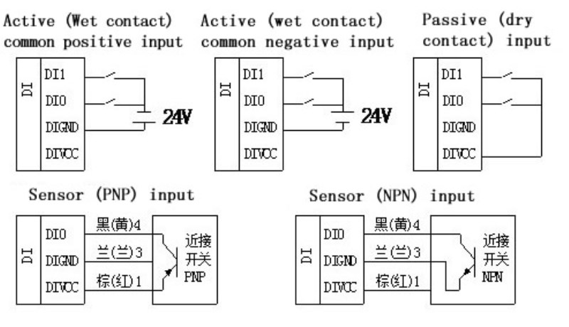
1) When set to active input, the open signal can be either a common or a common negative input simultaneously.
2) When the input is set to dry contact, simply connect the DI input to the DI common end.
Three. Technical indicators
project
|
parameter
|
Signal input
|
1Input channel: 16 trunk contact or wet node switch input.
2Signal type: automatic identification of common negative or common input polarity.
3Signal level: high level (10V ~ 30V) low level (0V ~ 3V)
FourSampling rate: 1000HZ
FiveIsolated voltage protection: 1000V
|
signal output
|
1Output channel: 16 way normally open relay output.
2Load capacity: resistive load 250V/3A inductive load 250V/1A
ThreeIsolated voltage protection: 1000V
|
Communication output
|
1Communication protocol: MODBUS-RTU
2Interface type: isolated RS485 communication, output interface adopts over voltage and over current double protection.
3Baud rate: 1200BPS, 2400bps, 4800bps, 9600bps, 19200bps.
38400bps, 57600bps, 115200bps
4Check bit: no check, parity check, odd check.
5Setting mode: module address, baud rate, parity bit through software settings.
6Communication distance: 9600bps 1200 meters.
SevenElectrical isolation protection: 1000V
|
Module size
|
Single module size: 145mm*90mm*40mm
|
Installation method
|
OneGuide rail installation: Standard 35mm DIN guide rail installation
TwoScrew fixing (long width):135mm*70mm
|
work environment
|
Temperature: -10 ~ +55 C humidity: 35~85% (no condensation).
|
Working power supply
|
1Power supply voltage: 10V~30V wide range of power supply, polarity protection with power supply
2Power consumption: less than 6W
|
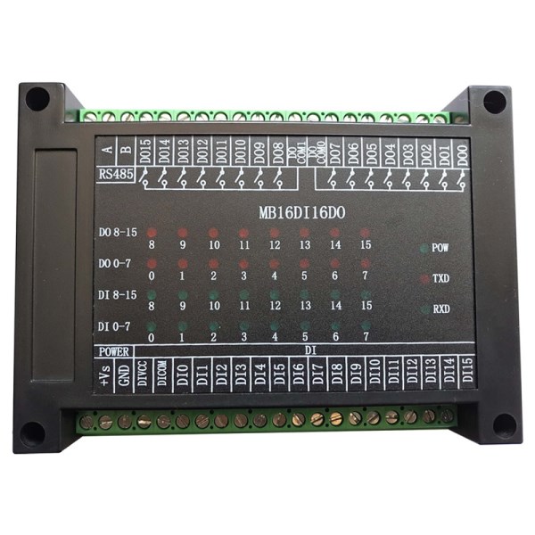
Four. Product appearance
Five. Module peripheral wiring diagram
1. Switch input wiring instructions
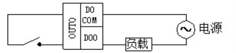
2. Relay output connection (normally open)
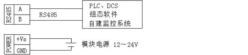
3. Communication and power connection
Six. Module indication light and switch function description
1. POW/SET;Module work status indication
A.Green lights: modules are working. B. red light: module has configuration parameter to write, need to power up again.
2. TXD/RXD:Communication status indication
A.Green light: communication receives data B. red light flashes: module is sending data.
C.The green light is always bright: the communication RS485 line on DATA+ and DATA- is reversed or the connection is broken.
3. Module left reset switch use
1) When the communication parameters (module address, baud rate, check bit) are not known or the communication parameters are misplaced, the solution is to reset the communication parameters. Five seconds later, the module [POW/SET] red indicator lights on and the reset switch is opened. At this time, the communication can be achieved. The parameters have been reset, so long as the power supply of the module is powered off and restarted once, then the communication parameters of the module have been reset.
2) After the reset, the communication parameters are: 1, baud rate: 9600bps, check bit: none.
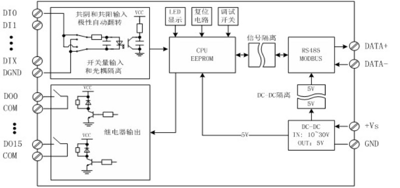
Seven. Principle block diagram
The second chapterModbusRegister and communication protocol specification
1. Module supported MODBUS function code
Register type
|
Function code
|
Functional code specification
|
Coil register
|
0x01H
|
Read one or more coil registers.
|
0x05H
|
Write a coil register.
|
0x0FH
|
Write one or more coil registers.
|
Input register
|
0x02H
|
Read one or more open registers.
|
Input register
|
0x04H
|
Read one or more input registers.
|
Hold register
|
0x03H
|
Read one or more holding registers.
|
0x06H
|
Write a data to hold register.
|
0x10H
|
Write one or more data to hold register.
|
Two. Register definition description
1. Coil registers (function codes can be used:0x01H,0x05H,0x0FH)
address
|
parameter
|
read/write
|
minimum value
|
Maximum value
|
Explain
|
00001
|
RO0
|
Read and write
|
0
|
1
|
Relay output0
|
00002
|
RO1
|
Read and write
|
0
|
1
|
Relay output1
|
00003
|
RO2
|
Read and write
|
0
|
1
|
Relay output2
|
00004
|
RO3
|
Read and write
|
0
|
1
|
Relay output3
|
00005
|
RO4
|
Read and write
|
0
|
1
|
Relay output4
|
00006
|
RO5
|
Read and write
|
0
|
1
|
Relay output5
|
00007
|
RO6
|
Read and write
|
0
|
1
|
Relay output6
|
00008
|
RO7
|
Read and write
|
0
|
1
|
Relay output7
|
00009
|
RO8
|
Read and write
|
0
|
1
|
Relay output8
|
00010
|
RO9
|
Read and write
|
0
|
1
|
Relay output9
|
00011
|
RO10
|
Read and write
|
0
|
1
|
Relay output10
|
00012
|
RO11
|
Read and write
|
0
|
1
|
Relay output11
|
|

