Condition:New
Type:Logic ICs
Model Number:MB10DI8RO
Operating Temperature:W
Supply Voltage:W
Dissipation Power:W
Color classification:Active input dry contact input
10 input 8 way relay output switch, can collect 8 dry or wet contact signal input node, you can set the common anode or common cathode, and automatically switch the polarity, no jumper switch. The use of Modbus-RTU communication, directly with the PLC, DCS and a variety of domestic soft
Purchase notice:
Please note it:
(default: Active input ) dry contact input Active input dry contact input
The first chapter product introduction
A.Summary
MB10DI8RO 10Switch input acquisition and 8 relay output module can collect 10 dry or wet signal contact node (active or passive input), can input common anode or common cathode, and automatically switch the polarity, no jumper switch. 10 way switch quantity signal collected data through the RS485 interface output; 8 way relay can be controlled via the MODBUS bus; control interface for the isolation of RS485, using Modbus-RTU communication, direct fit PLC, DCS and domestic various configuration software.
Open signal acquisition, relay output, power supply, RS485 communication electrical signals isolated from each other, the effective suppression of all types of serial mode and common mode interference, but also to ensure that the module works reliably.
Two.Characteristic
1.Using Modbus-RTU protocol.
2.Signal acquisition, relay output, power supply, RS485 communication electrical signals isolated from each other.
ThreeRS485The communication signal output interface is protected by the overvoltage and overcurrent.
4.Input signal type and communication format can be set by software.
FivePower polarity protection.
6.Open signal setting
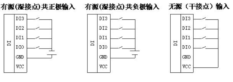
1)When set to the active input, input signal can also be used as input for a total of yin and yang or input, do not need to set the jumper, the internal polarity reversal function.
2)When set to dry contact input, as long as the short signal to the signal to the public side of the signal. However, users need to specify when buying, open into a common or isolated (isolated from the price higher).
Three.Technical index
project | parameter |
Signal input | 1Input channel: 10 way dry contact or wet node switch input 2Signal type: common yin or Yang input polarity identification 3Signal level: high level (30V ~ 10V) low level (0V ~ 3V) FourSampling rate: 1000HZ FiveIsolated voltage protection: 1500V |
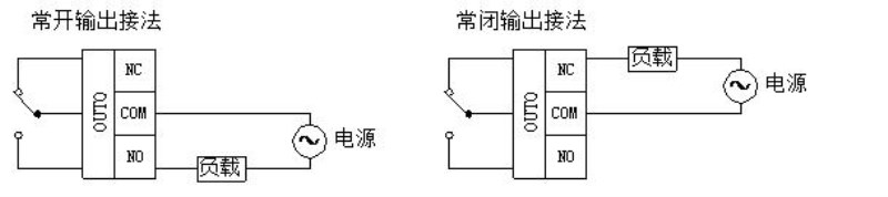
signal output | 1Output channel: 8 normally open relay output 2Load capacity: resistive load 250V/10A inductive load 250V/3A FiveIsolated voltage protection: 1500V |
Communication output | 1Communication protocol: MODBUS-RTU 2Interface type: isolated RS485 communication, the output of the interface using the overvoltage and overcurrent protection 3Baud rate: 1200BPS, 2400bps., 4800bps, 9600bps, 19200bps 38400bps57600bps, 115200bps. 4Check bit: no parity check, parity check 5. setting: module address, baud rate, parity bit is set up by the software 6Communication distance: 9600bps 1200 meters SevenElectrical isolation protection: 1500V |
Module size | Separate module size: 145mm*90mm*40mm |
Installation method | Standard DIN guide rail installation |
work environment | Temperature: -10 ~ +55 temperature humidity: 35~85% (not dew) |
Working power supply | 1Power supply voltage: 10V~30V wide range of power supply, with the power supply polarity protection 2Power consumption: less than 10W |
Four.Product appearance
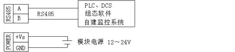
Five.Module peripheral wiring diagram
1.Switch input
2.Relay output method
3.Communication and power supply connection
Six.Module indicator lamp and switch function specification
1.POW/SET;Module working status indication
A.Green light: the module works in the running state. B. red light: the module is configured to write parameters, need to re power up.
2.TXD/RXD:Communication status indication
A.The green light flashes: the communication receives the data B. red light flashes: the module is sending data
C.The green light is always on: DATA+ and DATA- on the communication line RS485 line is connected to the reverse or the connection is broken.
3.Module right reset switch
1)When the communication parameters (module address, baud rate, parity bit) do not know or communication parameter misspecification, and can not establish contact module communication, the solution is to reset the communication parameters; we use the clip to hold the reset switch is not open, 5 seconds after the [POW/SET] module of the red indicator lights, release the reset switch, the communication the parameters have been reset, as long as the power supply module after the restart time, the communication parameters of the module has been reset.
2)Communication parameters after reset: Address: 1, baud rate: 9600bps, parity: No.
Seven.Principle block diagram

Eight.MODBUSRegister description
1.Module supports MODBUS function code
Code | Meaning | operation |
0x01H | Read more than one coil register | Read the values of one or more coil registers |
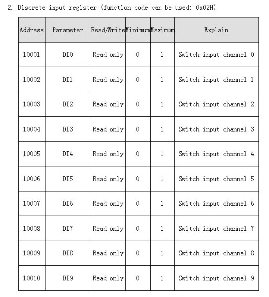
0x 02H | Read multiple input registers | Read one or more of the values of the open - in register |
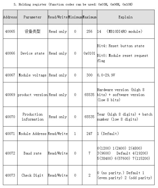
0x03H | Read more than one hold register | Read one or more of the value of the register. |
0x05H | Write a coil register | Write the value of a coil register |
0x 06H | Write a single hold register | Write a data to hold register |
0x0FH | Write one or more coil registers | Write one or more of the value of the coil register |
0x 10H | Write more than one hold register | Write one or more data to hold registers |
2.Register definition description
1)Coil register0x01H,0x05H,0x0FH)
address | parameter | read/write | minimum value | Maximum value | Explain |
00001 | RO0 | Read and write | 0 | 1 | Relay output0 |
00002 | RO1 | Read and write | 0 | 1 | Relay output1 |
00003 | RO2 | Read and write | 0 | 1 | Relay output2 |
00004 | RO3 | Read and write | 0 | 1 | Relay output3 |
00005 | RO4 | Read and write | 0 | 1 | Relay output4 |
00006 | RO5 | Read and write | 0 | 1 | Relay output5 |
00007 | RO6 | Read and write | 0 | 1 | Relay output6 |
00008 | RO7 | Read and write | 0 | 1 | Relay output7 |