Type:Voltage Regulator
Model Number:MB22DI4RO
Supply Voltage:10V-30V
Dissipation Power:5W
Operating Temperature:-10 to +55
Condition:New
Color classification:Open (active input) open (dry contact input)
Model:MB22DI4RO
Can choose:Active input(default),Dry contact input. Chapter 1 product introduction
. Summary
MB22DI4RO 22Switch input acquisition and 4 relay output module can collect 22 dry or wet signal contact node (active or passive input); as a dry contact input or sensor (NPN or PNP) input can be set is positive or negative input total jumper; as the active input polarity automatic conversion, no jumper switch; 4 way relay can be controlled via the MODBUS bus communication module; using Modbus-RTU, can be directly adapted PLC, DCS and various domestic configuration software etc..
Open signal acquisition, relay output, power supply, RS485 communication, electrical signals are isolated from each other, which effectively suppresses all kinds of series mode and common mode interference, and also ensures the module to work reliably.
. Characteristic
1. Adopting Modbus-RTU protocol.
2. Signal acquisition, relay output, power supply, RS485 communication, electrical signals are isolated from each other.
Three RS485The communication signal output interface adopts over-voltage and overcurrent double protection.
4. The type of input signal and the format of communication can be set by software.
Five Power polarity protection.
Six Open signal setting
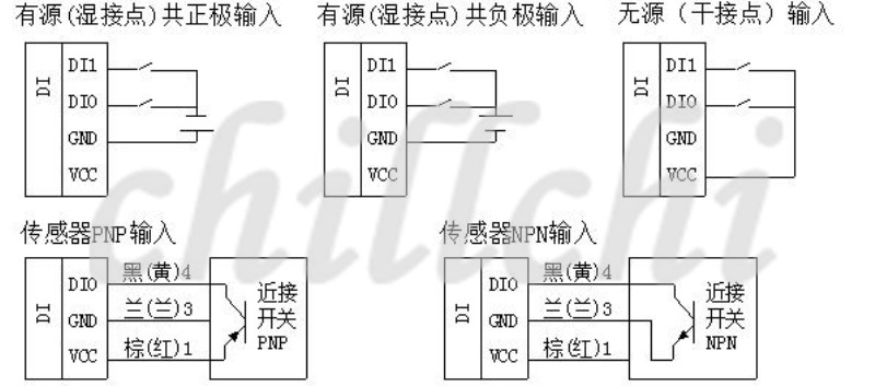
1) When set to the active input, input signal can also be used as input for a total of yin and yang or input, do not need to set the jumper, the internal polarity reversal function.
2) When set to dry contact input, as long as the short signal ends to the signal common end. But users need to indicate when they buy, whether they are open or segregated (the price of isolation is higher).
. Technical index
| project | parameter |
| Signal input | 1Input channel: 22 way dry contact or wet node switch input 2Signal type: common yin or Yang input polarity identification 3Signal level: high level (10V ~ 30V) low (0V ~ 3V) FourSampling rate: 1000HZ FiveIsolated voltage protection: 1500V |
| signal output | 1Output channel: 8 way normally open relay output 2Load capacity: resistive load 250V/10A inductive load 250V/3A FiveIsolated voltage protection: 1500V |
| Communication output | 1Protocol: MODBUS-RTU 2Interface type: isolated RS485 communication, output interface adopts over-voltage and overcurrent double protection 3Baud rate: 1200BPS, 2400bps, 4800bps, 9600bps, 19200bps. 4Parity bit: no parity check, even parity check, odd check 5Settings: module address, baud rate, parity bit, through the software settings 6Communication distance: 9600bps 1200 meters SevenElectrical isolation protection: 1500V |
| Module size | Individual module size: 145mm*90mm*40mm |
| Installation method | Standard DIN rail mounting |
| work environment | Temperature: -10 ~ +55 humidity: 35~85% (without dew) |
| Work power | 1Supply voltage: 10V~30V wide range power supply, with power polarity protection 2Power consumption: less than 5W |
. Module peripheral wiring diagram
1. Switch input connection description
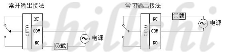
2. Relay output connection
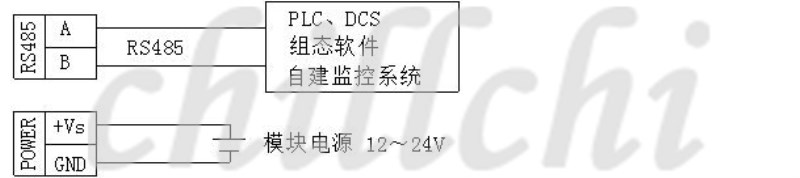
3. Connection of communication and power supply
. Module indicator and switch function description
1. POW/SET;Module work status indicator
A.The green light is on: the module is in operation. B. red light: modules have configuration parameters to write, need to re power.
2. TXD/RXD:Communication status indication
A.Green light flashing: communications receive data, B. red light flashing: module is sending data
C.The green light is always on: the communication line on DATA+ and DATA- meets the RS485 line or the connection is broken.
3. Module right reset switch
1) When the communication parameters (module address, baud rate, parity bit) do not know or communication parameter misspecification, and can not establish contact module communication, the solution is to reset the communication parameters; we use the clip to hold the reset switch is not open, 5 seconds after the [POW/SET] module of the red indicator lights, release the reset switch, the communication the parameters have been reset, as long as the power supply module after the restart time, the communication parameters of the module has been reset.
2) Reset communication parameters: Address: 1, baud rate: 9600bps, parity bit: No.
.Principle block diagram

Second chaptersModbusRegister and communication protocol specification
. MODBUS Register description
1. Module supported MODBUS function code
| Register type | Address range | Function code | Function code description |
| Coil register | 00001-00004 | 0x01H | Read one or more coil registers |
| 0x05H | Write a coil register |
| 0x0FH | Write one or more coil registers |
| Input register | 10001-10006 | 0x02H | Read one or more open input registers |
| Input register | 30001-30008 | 0x04H | Read one or more input registers |
| Hold register | 40001-40176 | 0x03H | Read one or more holding registers |
| 0x06H | Write a data to the hold register |
| 0x10H | Write one or more data to the hold register |
2. Register definition description
1) Coil register0x01H,0x05H,0x0FH)
| address | parameter | read/write | minimum value | Maximum value | Explain |
| 00001 | RO0 | Read and write | 0 | 1 | Relay output0 |
| 00002 | RO1 | Read and write | 0 | 1 | Relay output1 |
| 00003 | RO2 | Read and write | 0 | 1 | Relay output2 |
| 00004 | RO3 | Read and write | 0 | 1 | Relay output3 |
2) 0x02H)
| address | parameter | read/write | minimum value | Maximum value | Explain |
| 10001 | DI0 | read | 0 | 1 | Switch input channel 0 |
| 10002 | DI1 | read | 0 | 1 | Switch input channel 1 |
| 10003 | DI2 | read | 0 | 1 | Switch input channel 2 |
| 10004 | DI3 | read | 0 | 1 | Switch input channel 3 |
| 10005 | DI4 | read | 0 | 1 | Switch input channel 4 |
| 10006 | DI5 | read | 0 | 1 | Switch input channel 5 |
| 10007 | DI6 | read |

