Brand Name:icchipcn.com
Condition:New
Type:Logic ICs
Model Number:MB12RO
Supply Voltage:250V
type of output:12 normally open relay output 250V/10A
Communication type:RS485 MODBUS-RTU
Characteristic:Relay, RS485 communication, the main power of mutual isolation
Technology:Industrial patch design
MB12RO 12 way relay output module, relay can be controlled through the MODBUS bus, LED status indication, relay output control interface is convenient; the isolation of RS485, using Modbus-RTU communication, direct fit PLC, DCS and domestic various configuration software.
The first chapterProduct introduction
A.Summary
MB12RO 12Road relay output module, the relay can be controlled through the MODBUS bus, the control interface for the isolation of RS485, the use of Modbus-RTU communication, directly with the PLC, DCS, and various domestic configuration software, etc..
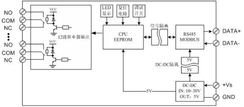
The relay output, the power supply and the RS485 communication electrical signals are isolated from each other, which can effectively restrain all kinds of mode and common mode interference, and ensure the reliability of the module.
Two.Characteristic
OneUsing Modbus-RTU protocol.
2.Relay output, power supply, RS485 communication electrical signals isolated from each other.
ThreeRS485The communication signal output interface is protected by the overvoltage and overcurrent.
4.Power polarity protection.
Three.Technical index
project | parameter |
signal output | 1Output channel: 12 normally open relay output 2Load capacity: resistive load 250V/10A inductive load 250V/3A FiveRelay coil and contact isolation voltage: 1500V |
Communication output | 1Communication protocol: MODBUS-RTU 2Interface type: isolated RS485 communication, the output of the interface using the overvoltage and overcurrent protection 3Baud rate: 1200BPS, 2400bps., 4800bps, 9600bps, 19200bps 38400bps57600bps, 115200bps. 4Check bit: no parity check, parity check 5. setting: module address, baud rate, parity bit is set up by the software 6Communication distance: 9600bps 1200 meters SevenIsolated voltage: 1500V |
Module size | Separate module size: 145mm*90mm*40mm |
Installation method | Standard DIN guide rail installation |
work environment | Temperature: -10 ~ +55 temperature humidity: 35~85% (not dew) |
Working power supply | 1Power supply voltage: 10V~30V wide range of power supply, with the power supply polarity protection 2Power consumption: less than 5W |
Four.Product appearance
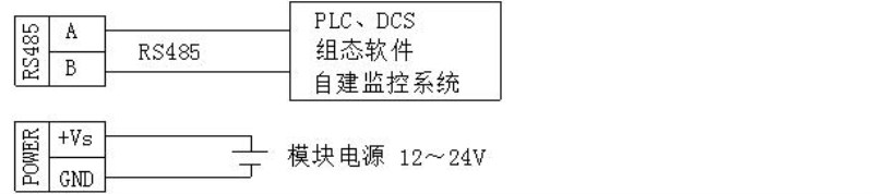
Five.External wiring diagram
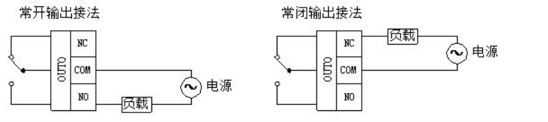
1.Relay output method
2.Communication and power supply connection
Six.Module indicator lamp and switch function specification
1.POW/SET;Module working status indication
A.Green light: the module works in the running state. B. red light: the module is configured to write parameters, need to re power up.
2.TXD/RXD:Communication status indication
A.The green light flashes: the communication receives the data B. red light flashes: the module is sending data
C.The green light is always on: DATA+ and DATA- on the communication line RS485 line is connected to the reverse or the connection is broken.
ThreeModule right reset switch
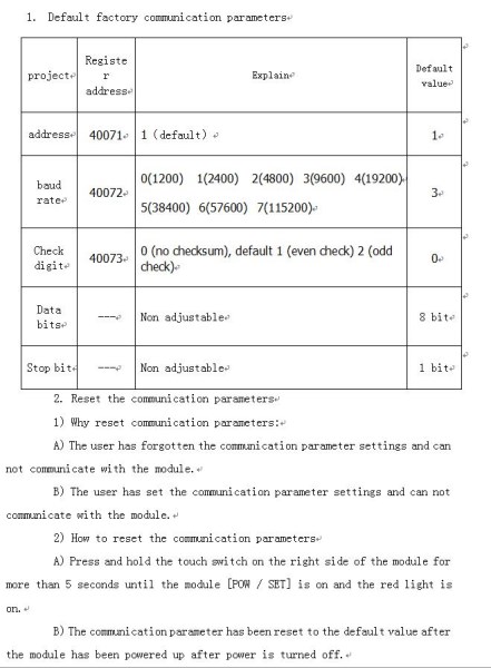
1)When the communication parameters (module address, baud rate, parity bit) do not know or communication parameter misspecification, and can not establish contact module communication, the solution is to reset the communication parameters; we use the clip to hold the reset switch is not open, 5 seconds after the [POW/SET] module of the red indicator lights, release the reset switch, the communication the parameters have been reset, as long as the power supply module after the restart time, the communication parameters of the module has been reset.
2)Communication parameters after reset: Address: 1, baud rate: 9600bps, parity: No.
Seven.Principle block diagram
Eight.MODBUSRegister description
1.Module supports MODBUS function code
Code | Meaning | operation |
0x01H | Read more than one coil register | Read the values of one or more coil registers |
0x03H | Read more than one hold register | Read one or more of the value of the register. |
0x05H | Write a coil register | Write the value of a coil register |
0x 06H | Write a single hold register | Write a data to hold register |
0x0FH | Write one or more coil registers | Write one or more of the value of the coil register |
0x 10H | Write more than one hold register | Write one or more data to hold registers |
2.Register definition description
1)Coil register0x01H,0x05H,0x0FH)
address | parameter | read/write | minimum value | Maximum value | Explain |
00001 | RO0 | Read and write | 0 | 1 | Relay output0 |
00002 | RO1 | Read and write | 0 | 1 | Relay output1 |
00003 | RO2 | Read and write | 0 | 1 | Relay output2 |
00004 | RO3 | Read and write | 0 | 1 | Relay output3 |
00005 | RO4 | Read and write | 0 | 1 | Relay output4 |
00006 | RO5 | Read and write | 0 | 1 | Relay output5 |
00007 | RO6 | Read and write | 0 | 1 | Relay output6 |
00008 | RO7 | Read and write | 0 | 1 | Relay output7 |
00009 | RO8 | Read and write | 0 | 1 | Relay output8 |
00010 | RO9 | Read and write | 0 | 1 | Relay output9 |
00011 | RO10 | Read and write | 0 | 1 | Relay output10 |
00012 | RO11 | Read and write | 0 | 1 | Relay output11 |
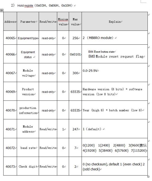
2)Hold register0x03H,0x06H,0x10H)
address | parameter | read/write | minimum value | Maximum value | Explain |
40065 | Equipment type | read-only | 0 | 256 | 2 (MB8ROModule) |
40066 | Equipment status | read-only | 0 | 0x0101 | Bit4Reset button stBit0Module reset request flag |
4006 |