Type:Logic ICs
Condition:New
Baby model:IO-XX-XX
This product is the perfect replacement for the brand of expensive PLC expansion module, is a low cost alternative solution. The opto-isolated switch input accepts both active and passive input signals. Output relay load capacity of 36V / 2A. This product uses the standard industrial MODBUS RTU as a slave device, with the PLC, MCGS, Kingview seamlessly connected, as its from the device to support up to 255 shop equipment 485 network.
IO-05-05 technical parameters:
> working voltage: DC12V~DC24V(recommended DC12V)
> working current: 150mA
Switch input mode:The input point is short and connected to the common end efficiently (such as the IN0 short access COM for the active input state)
> relay output: normally open contacts (e.g., K3'and K3 are a pair of normally open output contacts).
Relay node output capacity: DC30V/1A(Note: AC220V can not be connected to electricity)
> relay switch life: 100 thousand
Input terminal connection mode:
*24V - module working power supply, DC12V~DC24V
*GND - power supply
RS485 - *B signal line B
RS485 - *A signal line A
*IN0 - switch input channel 0
*IN1 - switch input channel 1
*IN2 - switch input channel 2
*IN3 - switch input channel 3
*IN4 - switch input channel 4
*COM - switch input common terminal
Output terminal connection mode:
K0/K0'- output relay 0 normally open contact
K1/K1'- output relay 1 normally open contact
K2/K2'- output relay 2 normally open contact
K3/K3'- output relay 3 normally open contact
K4/K4'- output relay 4 normally open contact
IO-10-10 technical parameters:
Mechanical size: 145x90x40mm (long x width x height)
> working voltage: DC12V~DC24V(recommended DC12V)
> working current: 150mA
> switch input mode: active / passive signal
> relay output: normally open contacts (e.g., K3'and K3 are a pair of normally open output contacts).
Relay node output capacity: DC30V/1A(Note: AC220V can not be connected to electricity)
> relay switch life: 100 thousand
Input terminal connection mode:
*24V - module working power supply, DC12V~DC24V
*GND - power supply
RS485 - *B signal line B
RS485 - *A signal line A
*IN0 - switch input channel 0
* * * * *
*IN9 - switch input channel 9
*VSS - switch input common terminal (short connected INx for valid input signal)
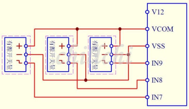
For the passive input signal: general is 2 lines, and the switch is in the form of machinery, V12 and VCOM can be shorted, and then switch the amount of two lines of a INx, a VSS (common), can realize the signal input.For the active input signal: the general is 3 lines: a power line (12V), a ground wire, a signal line, the power supply line and VCOM short, ground wire connected to VSS, signal line INx, you can achieve signal input.The following is a passive mechanical switch S0, S1, S2 input signal wiring diagram, the red line is the actual line, please refer to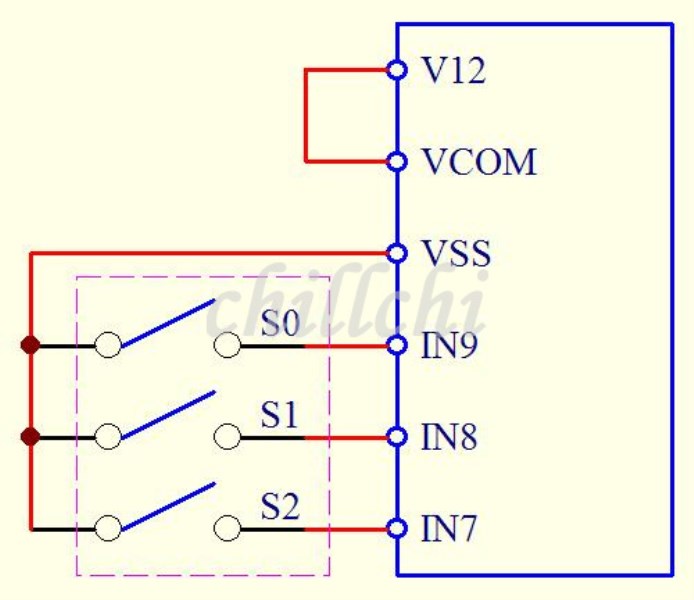
The following is the three active switch input signal wiring diagram, the red line is the actual line, please refer to
Output terminal connection mode:
K0/K0'- output relay 0 normally open contact
* * * * *
K9/K9'- output relay 9 normally open contact
General application note:Can control the signal lamp, electromagnetic valve, small motor, power off, speaker, output switch signal......

