Type:Logic ICs
Condition:New
I. Product Overview
l 16Opto-isolated digital inputs
l Using RS485 MODBUS RTU standard communication , networking and configuration software can be , PLC, industrial touch screen , etc.
l With communication and input status indicator
l Communication circuit lightning , anti-jamming design
l Signal acquisition and control can be widely used in industrial field devices
l Normal use of three-year warranty
Second, the main parameters
l 16 digital input channels (active low )
l Operating temperature range -20~ 70
l External power supply DC 9V ~30V / 2W
l 1500VDC isolation protection
l Standard DIN mounting rail or screw mounting
l Dimensions 125 × 73 × 35mm
Third, the interface definition
| AVcc | The positive terminal of the external power input |
| AGnd | Negative external power input terminal |
| DI_01 | The first digital inputs |
| DI_02 | The first two digital inputs |
| DI_03 | The first three digital inputs |
| DI_04 | 4 digital inputs |
| DI_05 | 5 digital inputs |
| DI_06 | 6 digital inputs |
| DI_07 | The first seven digital inputs |
| DI_08 | The first eight digital inputs |
| DI_09 | The first nine digital inputs |
| DI_10 | The first 10 digital inputs |
| DI_11 | 11 digital inputs |
| DI_12 | 12 digital inputs |
| DI_13 | The first 13 digital inputs |
| DI_14 | 14 digital inputs |
| DI_15 | 15 digital inputs |
| DI_16 | 16 digital inputs |
| 485A | RS485Signal A + |
| 485B | RS485Signal B- |
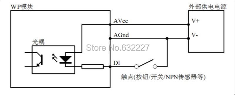
Fourth, the digital input application diagram
Five , communications instructions
1,Communication Parameters ( factory default ): 9600, N, 8,1
| Parameters | Description |
| 9600 | Baud Rate |
| N (No parity ) | Parity bit |
| 8 | Data bits |
| 1 | Stop bits |
2, Digital input signal acquisition command :
Send : 01 02 00 00 00 10 79 C6 ( case / 16 hex )
| Data | Bytes | Data Description | Remarks |
| 01 | 1 | Module address | Address range 01-FE |
| 02 | 1 | Function Code | 02Read input bits |
| 0000 | 2 | Enter the address (1x type ) | 0000-Input bit starting address |
| 0010 | 2 | Read input bit length | 0010-Read 16 input bits |
| 79C6 | 2 | CRCChecksum | All the data in front of the CRC |
Receive:01 02 02 21 A0 A1 90( Example / 16 hex )
| Data | Bytes | Data Description | Remarks |
| 01 | 1 | Module address | Address range 01-FE |
| 02 | 1 | Function Code | 02Read input bits |
| 02 | 1 | Bytes | 02Read two bytes in length |
| 21A0 | 2 | Read data | 21A0-Reads the input bit status |
| A190 | 2 | CRCChecksum | All the data in front of the CRC |
Data read "21" , is converted into a binary number " 00100001 " , from left to right correspond to the state of 8 digital input signals DI_08-DI_01 , the data read "A0", converted into 2 into system number is " 10100000 " , from left to right respectively state 8 digital input signals DI_16-DI_09 , that DI_16, DI_14, DI_06, DI_01 input , no input other channels
3,Module address setting command :
Send: 0,006,006,400,010,804 ( case / 16 hex )
| Data | Bytes | Data Description | Remarks |
| 00 | 1 | Module address | 00-Bulk Address |
| 06 | 1 | Function Code | 06-Write single register |
| 0064 | 2 | Register Address (4x type ) | 0064-Modify module address |
| 0001 | 2 | Write data | Setting module new address , range 0001-00FE |
| 0804 | 2 | CRCChecksum | All the data in front of the CRC |
Receive: 0,006,006,400,010,804 ( case / 16 hex )
The command said the directive issued to a module , the module's new address is set to 01 , this setting can save the loss of power ; default address of the module is 01 , when the need for networking multiple modules , each module can address the individual settings , because the use of the mass addresses, so the setting requires 485 network can have only one module , otherwise it will create 485 network addresses of all modules are set to the same address , please use caution this instruction ; when the module receives the correct after the command , make the appropriate action based on the command and response command sent back to the host , indicating successful communication
4Communication parameter setting commands :
Send: 0,106,006,500,021,814 ( case / 16 hex )
| Data | Bytes | Data Description | Remarks |
| 01 | 1 | Module address | Address range 01-FE |
| 06 | 1 | Function Code | 06-Write single register |
| 0065 | 2 | Register Address (4x type ) | 0065-Modify the communication parameters |
| 0002 | 2 | Write data | 0001-Set communication parameters 4800, N ( no parity ) , 8,1 0002-Set communication parameters 9600, N ( no parity ) , 8,1 |

