Type:Logic ICs
Condition:New
Color classification:Display without display screen
15mm:without display
20mm:with display
Chapter 1 product introduction
1. Summary
MB10TC 10High precision acquisition module for road thermocouple.8Kind of thermocouple(J/K/T/E/R/S/B/N)The temperature of collection is high.10roadChannels can collect the same type of thermocouples, or each channel can collect different types of thermocouples; the analog signal data collected by isolationRS485Interface output; module adoptionModbus-RTUCommunication can be adapted toPLC,DCSAnd various configuration software.
Signal acquisition, CPU and power input, RS485 communication electrical signals are isolated from each other, effectively suppressing all kinds of serial mode and common mode interference, ensuring the accuracy of data, but also ensuring the reliable work of the module.
Two. Characteristic
1. The standard Modbus-RTU protocol is adopted.
2. 10 thermocouples can be collected, and each channel is isolated from each other.
Three The input signal types of channels can be set according to their needs..
4. High-precision signal acquisition: high-precision 24-bit AD and voltage reference, voltage reference temperature coefficient 10PPM/(?) max.
Five Independent high precision cold end compensation with accuracy of + 0.5C.
Six Safety: signal collection, signal output, power supply, RS485 communication and electrical signals are isolated from each other.
7. Communication protection: RS485 communication signal output interface adopts over voltage and over current double protection.
Eight The input signal type and communication format can be set by software.
Nine Power polarity protection.
Three. Technical indicators
| project | parameter |
| AI Signal input | 1Input channel: 10 way.Channel isolationTemperature collection 2Input signal type: 8 thermocouples (J/K/T/E/R/S/B/N) ThreeSampling rate: 10 channels per 800mS collection. 4.AD resolution: 24position FiveSignal acquisition circuit and power input isolation voltage protection: 1000V |
| RS485 Communication output | 1Communication protocol: MODBUS-RTU 2Interface type: isolated RS485 communication, output interface adopts over voltage and over current double protection. 3Baud rate: 1200BPS, 2400bps, 4800bps, 9600bps, 19200bps 38400bps, 57600bps, 115200bps. 4Check bit: no check, parity check, odd check. 5Setting mode: module address, baud rate, parity bit can be set by software. 6. RS485Circuit and power input isolation voltage protection: 1000V |
| Module size | A.Single module size: 104mm*72mm*26mm B.Terminal and guide box size: 124mm*72mm*45mm |
| Installation method | Standard DIN guide rail installation (35mm guide or high and low guideway) |
| work environment | Temperature: -10 ~ +55 C humidity: 35~85% (no condensation). |
| Working power supply | 1Power supply voltage: 10V~30V wide range of power supply, polarity protection with power supply 2Power consumption: less than 3W |
Four. measurement accuracy
| Input type | measuring range | Display resolution | accuracy |
| Thermocouple | J(-200-1200 C) | 0.1C | 0.4 degrees centigrade |
| K(-200-1370 C) |
| T(-200-400 C) |
| E(-200-950 C) |
| R(-20-1750 C) | 0.6 degrees centigrade |
| S(-20-1750 C) |
| B(600-1800 degrees Celsius) |
| N(-250-1300 C) | 0.4 degrees centigrade |
| Cold end compensation | -20 - 85 degrees centigrade | 0.1Centigrade | Cold end compensation: + 0.5 C |
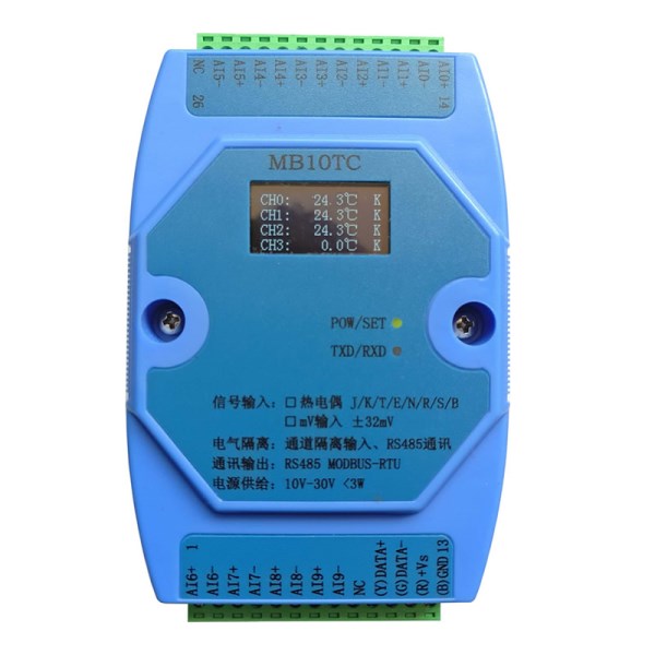
Five. Product appearance and peripheral wiring diagram
Six. Module indication light and switch function description
1. POW/SET;Module work status indication
A.Green lights: modules are working. B. red light: module has configuration parameters written, need to power up again.
2. TXD/RXD:Communication status indication
A.Green light: communication receives data B. red light flashes: module is sending data.
C.The green light is always bright: the communication RS485 line on DATA+ and DATA- is reversed or the connection is broken.
Three Module right reset switch
A. When the communication parameters (module address, baud rate, check bit) are not known or the communication parameters are misplaced, the solution is to reset the communication parameters. Five seconds later, the module [POW/SET] red indicator lights on and the reset switch is opened. At this time, the communication can be achieved. The parameters have been reset, so long as the power supply of the module is powered off and restarted once, then the communication parameters of the module have been reset.
B. After the reset, the communication parameters are: 1, baud rate: 9600bps, check bit: none.
4. OLEDDisplay instructions
| Display effect | Explain |
| CH0:123.5Centigrade K | Channel 0, the current channel temperature is 123.5.CentigradeThe thermocouple is K type. |
| CH0:-123.5Centigrade K | Channel 0, the current channel temperature is -123.5CentigradeThe thermocouple is K type. |
| CH0: -- -. -CentigradeK | Channel 0, the current channel thermocouple is disconnected and the thermocouple is K. |
| CJT: 23.5Centigrade | Current thermocouple cold junction compensation temperature |
Seven. Typical application wiring diagram
1. Thermocouple input wiring

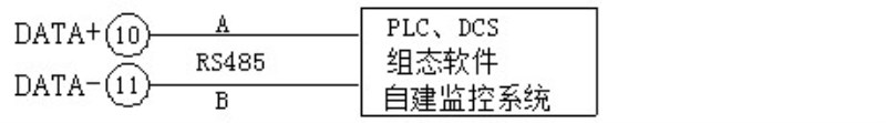
2. RS485Communication wiring diagram
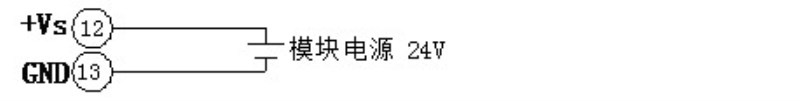
3. Module power input wiring
Eight. Terminal definition
| terminal | Name | Explain | | terminal | Name | Explain |
| 1 | AI6+ | Thermocouple Input Channel 6 positive end | 26 | NC | empty |
| 2 | AI6- | Thermocouple Input Channel 6 negative end | 25 | AI5- | Thermocouple Input Channel 5 negative end |
| 3 | AI7+ | Thermocouple Input Channel 7 positive end | 24 | AI5+ | Thermocouple Input Channel 5 positive end |
| 4 | AI7- | Thermocouple Input Channel 7 negative end | 23 | AI4- | Thermocouple Input Channel 4 negative end |
| 5 | AI8+ | Thermocouple Input Channel 8 positive end | 22 | AI4+ | Thermocouple Input Channel 4 positive end |
| 6 | AI8- | Thermocouple Input Channel 8 negative end | 21 | AI3- | Thermocouple input channel 3 negative end |
| 7 | AI9+ | Thermocouple Input Channel 9 positive end |

