Type:Logic ICs
Condition:New
First, product overview
l 4K type thermocouple input
l 4Road light electrically isolated digital input and 4 way photoelectric isolated digital output (NPN transistor collector output)
l Using MODBUS RTU RS485 standard communication, can be configured with configuration software, PLC, industrial touch screen and other networking
l With communication and input and output status indicator
l Design of lightning protection and anti interference for communication circuit
l Signal acquisition and control can be widely used in industrial field equipment.
l Normal use of three years warranty
Two, the main parameters
l Thermocouple Inputpassageway4Road (K type)
l Measuring range0~ 1000
l Temperature measurement accuracy of 2C
l Temperature resolution 1C
l Digital input channel 4 (active low)
l Digital output channel 4 (NPN transistorOpen collectorOutput,Five00mA)
l Operating temperature range -20 ~ 70
l External power supply 9V DC ~ 30V/2W
l Isolation protection 1500VDC
l Installation method standard DIN guide rail mounting or screw mounting
l Appearance size 125 * 73 * 35mm
Three, interface definition
| AVcc | External power input positive end |
| AGnd | External power input negative |
| T_1+ | First way K type thermocouple input positive end |
| T_1- | First way type K Thermocouple Input negative end |
| T_2+ | Second way K type thermocouple input positive end |
| T_2- | Second way type K Thermocouple Input negative end |
| T_3+ | Third way K type thermocouple input positive end |
| T_3- | Third way type K Thermocouple Input negative end |
| T_4+ | Fourth way K type thermocouple input positive end |
| T_4- | Fourth way type K Thermocouple Input negative end |
| DI_01 | First way digital input |
| DI_02 | Second way digital input |
| DI_03 | Third way digital input |
| DI_04 | Fourth way digital input |
| DO_01 | First way digital output |
| DO_02 | Second way digital output |
| DO_03 | Third way digital output |
| DO_04 | Fourth way digital output |
| 485A | RS485Signal A+ |
| 485B | RS485Signal B- |
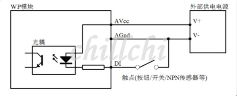
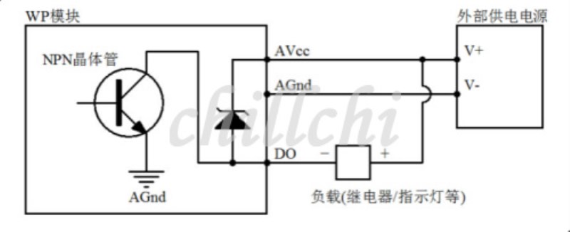
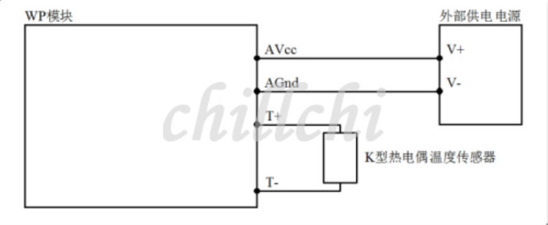
Four, digital quantity / temperature sensor application schematic diagram
1Digital input application
2Digital output application
3Temperature sensor applications
Five, communication instructions
1,Communication parameter description (ex factory value):9600, N,Eight, 1
| parameter | Explain |
| 9600 | baud rate |
| (NNo verification | Check bit |
| 8 | Data bits |
| 1 | Stop bit |
2,Thermocouple input signal acquisition command:
Send: 0103000000044409 (/16 system)
| data | byte | Data description | Remarks |
| 01 | 1 | Module address | Address range 01-FE |
| 03 | 1 | Function code | 03-Read register |
| 0000 | 2 | Register address (type 4x) | 0000-Analog input start register |
| 0004 | 2 | Read length | 0004-Read 4 registers |
| 4409 | 2 | CRCCheck code | All data in front of the CRC check code |
Receive: 010308002000 FF 1F FF FF FF 2043(case /16 system)
| data | byte | Data description | Remarks |
| 01 | 1 | Module address | Address range 01-FE |
| 03 | 1 | Function code | 03-Read register |
| 08 | 1 | Number of bytes | 08-Read 8 bytes in length |
| 0020 001F FFFF FFFF | 8 | Read data | 0020 -Read temperature sensor 1 data 001F -Read temperature sensor 2 data - FFFFRead temperature sensor 3 data - FFFFRead temperature sensor 4 data |
| 2043 | 2 | CRCCheck code | All data in front of the CRC check code |
Read the data for the 16 hex, into a 10 system after processing according to the data:
AWhen the data is equal to 65535, the temperature sensor is not connected
BWhen the data is not equal to 65535, the data read is the measured temperature
3Digital input signal acquisition command:
Send out: 01020000000479 C9(case /16 system)
| data | byte | Data description | Remarks |
| 01 | 1 | Module address | Address range 01-FE |
| 02 | 1 | Function code | 02-Read input bit |
| 0000 | 2 | Input address (type 1x) | 0000-Input bit start address |
| 0004 |

