Condition:New
Type:Logic ICs
contact form:Conversion type
15mm means only module
20mm means module withHeatsink(15A/35A/50A/70A)
or withheatsink and fan(90A/120A/150A)

An overview
1,LSC-Series of integration of three phase rectifier voltage regulator module adopts the imported large scale integrated circuit design, internal set three-phase zero crossing detection circuit, phase shift Control circuit, trigger drive circuit, six road one-way Controlled silicon full Control bridge, six roadRCRC absorption circuit and a power circuit is equal to one, in the automatic or manual adjustment of the input Control, three-phase can change the trigger pulse signal to Control internal thyristor conduction angle and realize three-phase alternating current is directly converted into amplitude stepless adjustable pulsating direct current voltage, on load voltage from0VFull range adjustment to the full voltage of the power grid. Module is typically used in a variety of power supply, voltage regulator, DC motor, excitation, welding, electroplating, charging, etc..
2,0-5Vdc,0-10Vdc,4-20mACompatible input automatic Control mode, can also be used to manually Control. The input range is wide, the output regulation precision is high, and the anti-interference ability is strong. Power up no instant impact output.
3,YtypeModule built-in high performance switching power supply. No external synchronous transformer, no external DC power supply.
4Module useSMTTechnologyDCBCeramic substrate, small size, less external wiring, stable performance, easy to use, high reliability.
5Module hasLEDPower indication and output regulation indication.
6The module has a built-in SCR protection circuit, without external connection.
7The module is suitable for three-phase four wire circuit.380V.10%Frequency:50Hz.Into the line of three-phase AC circuitR,S,TThe phase requirements. Other low voltage use, can also be customized.
8ReCOMmended for general useYModule type.If the application system does notNLine, can chooseBModule type,Suitable for three-phase three wire circuit. But at this time need to pick one380V/15V,2WA small transformer, or a DC power supply, as a module of the working power.
9,Control the input terminal and the switch between the input power and between the high voltage main loop and full isolation design, insulation dielectric withstanding voltage greater than2000 Vac.
Two module load output current levels and models are as follows:
Electric current
Model (three phase four wire system)
Model (three phase three wire system)
50A
LSC-TH3P50FY
LSC-TH3P50FB
70A
LSC-TH3P70FY
LSC-TH3P70FB
90A
LSC-TH3P90FY
LSC-TH3P90FB
120A
LSC-TH3P120FY
LSC-TH3P120FB
150A
LSC-TH3P150FY
LSC-TH3P150FB
Note:150AMore than a large current can be used by the COMpany "three phase triggerLSJK-T3SCRF+Controllable silicon Controlled or semi Controlled COMbination mode, high cost, small fault.
Instructions
1Unique fully COMpatible input Control mode,0-5Vdc,0-10Vdc,4-20mA,1-5Vdc,0-10mAAnd other automatic methods are able to adapt, do not need special custom, can also be used to manually control the potentiometer. The input range is wide, the output regulation precision is high, and the anti-interference ability is strong.
Manual control of the potentiometer: according to the icon, the middle end of the potentiometer is connected to the modulecontThe two ends of the potentiometer are respectively connected with the module.COMEnd and+5VEnd. When the control sidecontfrom0-5VdcChanging the voltage on the load from0V to the maximum linear adjustable,contThe higher the terminal voltage, the greater the output of the module.+5VVoltage by the module itself, without the need for external supply, with only hand control potentiometer with and without it, the selected resistance value of the potentiometer in2-10KInter. When this way is used4-20mA'and' the end '0-10VdcThe end shall beCOMEnd to end.
2,0-5VdcControl mode: according to the icon, can be accepted0-5VdcAnalog signal, input control positivecontNegative electrodecomInternal modulecontEnd relativecomThe input impedance is greater than30KOmega. When this way is used4-20mA'and' the end '0-10VdcThe end shall becomEnd to end.
3,0-10VdcControl mode: according to the icon, can be accepted0-10VdcAnalog signal, internal module0-10VdcEnd relativecomThe input impedance is greater than15KOmega. When this way is used4-20mAThe end shall becomEnd to end.
4,4-20mAControl mode: according to the icon, can be accepted4-20mAAnalog signal, internal module4-20mAEnd relativecomThe input impedance of the250Omega. When this way is used0-10VdcThe end shall becomEnd to end.
5,0-10mAControl mode: according to the graphic, this method should be used in the modulecontWith the end ofcomEnd to end500Omega,1/2WResistance, when input0mAtimecontintention0VdcWhen input10mAtimecontintention5Vdc.
2Function end relativecomEnd must be positive,comThe end of the negative electrode, such as the polarity of the module main circuit output end may be out of control.
3, the control characteristics of the end of each function module are positive, that control voltage is higher, higher output voltage of the module of high voltage main loop.
4, when the output end and the General Assembly electrolytic capacitor filter, due to mutations in the voltage on both ends of the capacitor can not be, this high voltage, large capacitive occasion is likely to cause modules over-current damage, so module of electricity shall ensure the control endcontVoltage in0Vor4mAAfter power up,contShall be gradually increased from the low position to ensure that the capacitor impact current is minimized.
5At some point, it is better to use an input control mode, if two or more ways to use the same time, it is generally a strong input signal a major role. The module can be used for both manual and automatic functions, and the function can be switched by a double throw switch.
6If silicon controlled silicon in the module can be long time output large current (i.e. main circuit input voltage is very high, the output voltage is low), which may lead to serious heating of the module. If the actual use of the load voltage is low, the voltage can be reduced by using a three-phase transformer, and then the voltage of the rectifier can be used.LSC-TH1PxxFYandLSC-TH0PxxFYLow pressure series.

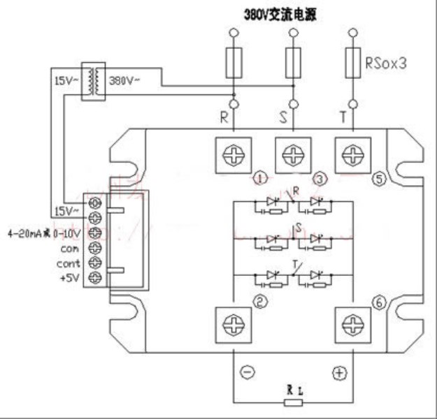
The main circuit power output application circuit wiring:
Installation: wall mounted vertical installation. Connection screw to screw down, the power supply for the upper and lower.
Into the line of three-phase AC circuitR,S,TThe phase conductor thickness requirements, according to the actual use of the current selection.
NThe wire is only used for internal switch power supply.1Square fine wire,NBetween the line and the input control end for the isolation of insulation design.
Over current protection: in the use of the process if the flow phenomenon, should first check the load with no short circuit, etc.. Can be in the moduleIncoming lineR,S,TEnd beforeInstall fast fuse, the specification can be according to the actual load current1.5Times matching.
5The module should be used in conjunction with the radiator, and there is enough heat radiation space between the cabinet and the other devices. When necessary, can be installed fan forced cooling. The cooling effect is not only concerned with the actual use of the size of the current and the radiator, with ambient temperature (summer and winter), ventilation conditions (natural cooling, forced cooling air volume), and install density and other factors are related. The third, threeR,S,TThe input end of the DC output is negative, the output DC positive.
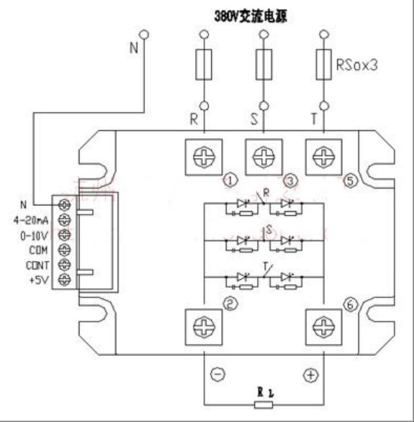
BtypeThe module is applied to three-phase three wire circuit wiring diagram.NLine)
At this time need to connect a power for2WThe380V/15VSmall transformer, or DC power supply, as a module of the working power supply.
Input control terminal0-5Vand4-20mAFunctional reserve. Must use0-10VControl function, please specify when ordering.

