Brand Name:icchipcn.com
Condition:New
Type:Logic ICs
Product Feature:
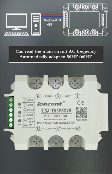
■ Support RS485 communication
■ 32-bit imported chip
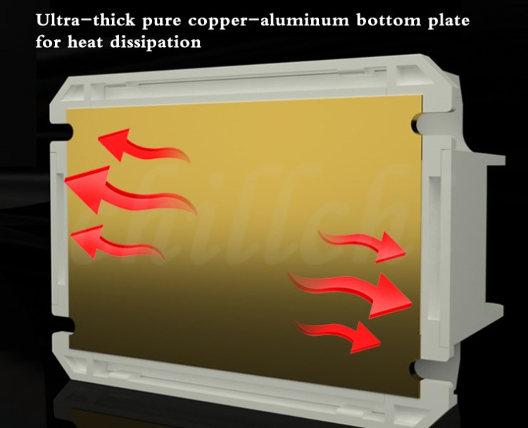
■ Positive copper design
■ 10000:1 resolution
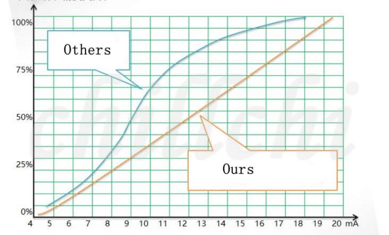
■ Linear compensation curve
■ Overheating protection
■ Custom soft start
■ Stepless voltage regulation
■ Analog control
■ Linear power compensation
■ Linear voltage compensation
Technical parameter
Control parameter
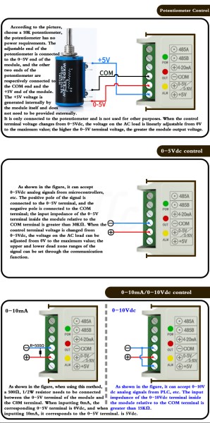
Input voltage control: 0-5V, 0-10V
Input current control: 4-20mA
Manual potentiometer control: 10KΩ
485 Communication Control: Reference Manual
LED indicator: POW, OUT, ALM three-color indicator
Output parameters
Rated working voltage: 380±10%Vac
Grid frequency: 50HZ
Inrush current (one week of grid): 800%
Minimum load current: 100mA
Off-state leakage current: <12mA
Static voltage rise rate dVs/dt:>200V/us (enhanced)
Commutation voltage rise rate dVc/dt:>200V/us (enhanced)
Adjustment response time: <10ms
Turn off maximum delay: <10ms
Other parameters
Dielectric withstand voltage (between input, output and shell): ≥2000Vac
Insulation resistance (between input, output and case)>1000MΩ (500Vdc)
Working environment temperature: -40℃-+60℃
Cooling method: radiator, forced air cooling
More features
◆ 1:10000 resolution
The conduction angle of the thyristor is divided into 10,000 parts, and the voltage is precisely regulated, which greatly improves the heating accuracy of the equipment.
◆ Readable device temperature
Read the temperature of the regulator radiator at any time (0-99°C)
◆ Soft start function
Soft start time can be set to any value within 0-300S;
The soft-start function can be set to be on or off.
◆ Customized overheat protection threshold
Overheat protection temperature value (10-100 degrees) can be set through 485 communication;
The regulator triggers overheat protection at 75 degrees by default.
◆ Reversible output
The default is forward output. If it is set to reverse output, the larger the analog signal, the smaller the regulator output voltage.
There are three ways to read and write module output through 485 communication:
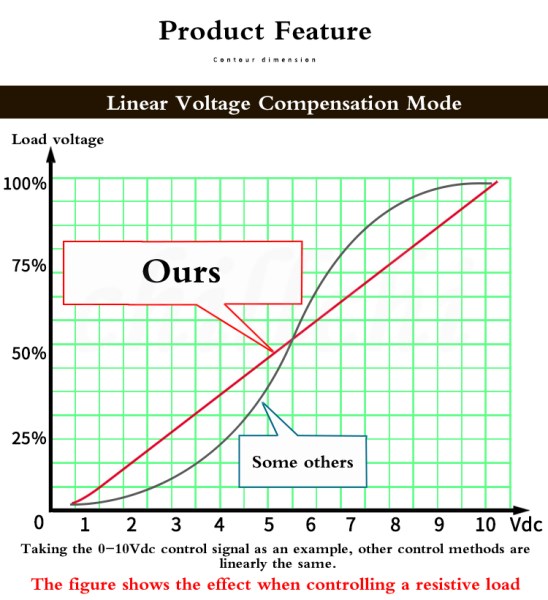
①No wireless compensation:
The output voltage linearity of the wireless compensation is shown as the black line in the above figure;
② Voltage linear compensation:
The output voltage linearity is almost an ideal straight line;
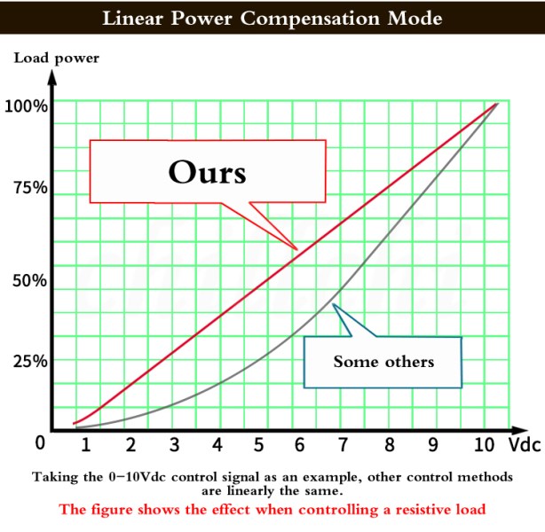
③Power linear compensation:
The output power linearity is almost an ideal straight line;
The default state of the module is voltage linear compensation. If you need to change it, you can arbitrarily modify the output mode of the module through 485 communication.
Output upper and lower limit read and write
The upper and lower limits can be output through the 485 communication read-write module
①Output upper limit setting:
The output upper limit can be set from 0-100, the default is 100, that is, the output upper limit is 100%. Note that the output upper limit should be larger than the output lower limit;
②Output lower limit setting:
The output lower limit can be set from 0-100, the default is 0, that is, the output lower limit is 0%. Note that the output lower limit should be smaller than the output upper limit;
Example: 485 communication write output upper limit is set to 80, output lower limit is set to 20, and other parameters of the module are default values.
Then the control signal increases or decreases, and the output of the module can only be adjusted in the range of 20%-80% (the output of the module is turned off when the signal is disconnected or the minimum is 0).
Signal dead zone upper and lower limits read and write
The upper and lower limits of the signal dead zone of the module can be read and written through 485 communication
①Signal dead zone upper limit setting:
The upper limit of the signal dead zone can be set from 0 to 100. The default value is 97, that is, more than 97% of the semaphore is the signal dead zone to ensure the maximum output.
②Signal dead zone lower limit setting:
The lower limit of the signal dead zone can be set from 0 to 100. The default value is 3, that is, less than 3% of the semaphore is the signal dead zone to ensure shutdown.
Example: 485 communication write signal dead zone upper limit is 80, signal dead zone lower limit is set to 20, other parameters are default values. If using 0-10Vdc analog control.
Then the control terminal signal 0-2Vdc module does not output 2Vdc-8Vdc as an adjustable area, the module output linearly increases 8Vdc-1OVdc module output maximum value
Product Advantage
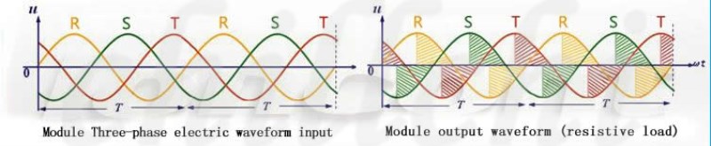
LSA series three-phase fully isolated integrated AC voltage regulator module adopts imported large-scale integrated circuit design. The internal three-phase phase shift trigger circuit, one-way thyristor, RC RC absorption circuit and power circuit are integrated into one, which can be automatic or manual. Adjust to change the voltage on the load to adjust the three-phase output power. That is, under the input control, a strong trigger pulse signal with three-phase changeable conduction angle is generated to control the internal thyristor separately, and the three-phase load voltage is steplessly adjustable from zero volts to the full voltage of the power grid.
Features
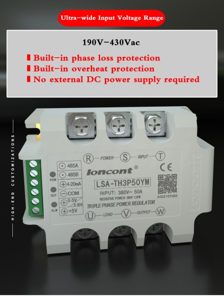
1. No external synchronous transformer is required, and no external input 12V DC power supply is required. It is very easy to use.
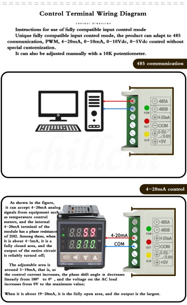
2, fully support 4-20mA, 0-5Vdc, 0-10Vdc, 1-5Vdc, O-10mA and other input automatic control mode, can also be manually controlled. The input adjustment range is wide, the output adjustment precision is high, the three-phase symmetry is good, and the anti-interference ability is strong.
3. There is a phase loss protection function. When the module is out of phase due to three-phase electrical input or the voltage is unstable, the module will immediately turn off the three-phase output to avoid load damage, so as to avoid production loss.
4, there is overheat protection function, when the module due to poor heat dissipation, the bottom plate temperature exceeds 75 degrees, immediately turn off the thyristor output to avoid module damage.
5. The module adopts the original single-chip linear compensation circuit, and the output characteristic curve is close to the ideal straight line when the resistive load is connected. The input control has a wider adjustment range, a finer signal resolution, and a higher output voltage regulation accuracy.
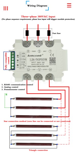
6, the product is suitable for three-phase four-wire system, AC 380V ± 10% frequency: 50Hz. The phase sequence is automatically discriminated, and the incoming lines R, S, and T of the circuit have no phase sequence requirements. If the user needs to use it under other voltages, or if there is no zero line, it can be customized to our company.
7. The module control phase shifting circuit and the AC high-voltage input and output main circuit are designed to fully isolate the upper and lower two-layer circuit board structure, and the insulation medium withstand voltage is greater than 2000Vac. The power thyristor chip and the DCB ceramic substrate have excellent heat dissipation, and the heat is not transmitted to the control circuit, and the technical parameters have small temperature drift and strong anti-interference ability.
8. It adopts high-power thyristor chip and low thermal resistance copper-ceramic bond (DCB) base plate, which is small in size, stable in performance and high in reliability.
9. The module has a green power indicator POW and a red output adjustment indicator OUT, as well as a protection status indicator ALM, and the working status is visually displayed.
10. The product can adapt to inductive loads such as transformers or resistive loads such as electric heating. The load can be in shape or Y-connected. The balanced three-phase load center point does not need to be connected to the N line during the Y-connection.
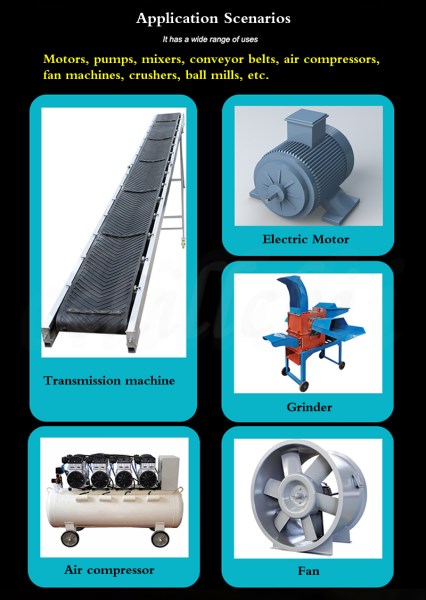
11. The product is also suitable for the speed regulation of small power three-phase torque motor, and the speed regulation of fans, pumps, etc., and can also be applied to the slow start of AC motors.
Model Selection Rules
Calculate the current size
Equipment current ÷ coefficient = specification current
Specification current x factor = device current
Note: resistive load factor 0, 2-0.33, inductive load factor 0.1-0.2
Note: The specification current is the inrush current, not the long-term working current
Note: The device current is the rated working current of the load or the actual measured current
Example 1: Three-phase 380V9KW electric heating tube, the actual line current is about 13A
Divide by the coefficient 0.33, you can choose 40A products
Example 2: Three-phase 380V9KW transformer, the actual line current is about 13A
Divide by the coefficient 0.2, you can choose 70A products
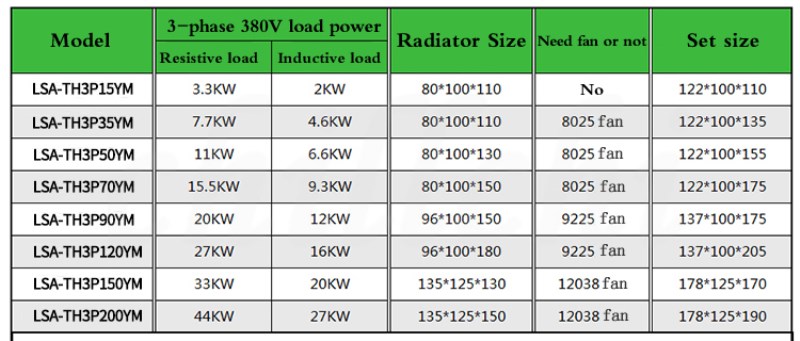
If the rated working current of the equipment is above 10A, it needs to be equipped with a radiator, and if it is above 20A, it needs to be equipped with a forced cooling fan.
Resistive loads refer to: incandescent lamps, resistance wires, ovens, heating rods. The resistive load is selected according to the factor of 3
Inductive load refers to: transformer, coil, fan motor, water pump motor. The inductive load is selected according to the multiplication factor.
Resistive loads with large changes in cold and heat resistance, such as silicon carbon rods, silicon molybdenum rods, platinum P leaves, and graphite, should be selected according to a factor of 4.
Unusable loads: household appliances (such as televisions, computers), electrical appliances with switching power supplies, no no-load is allowed.