Condition:New
Type:Logic ICs
ECANPro
USB to CANadapter
UserManual

Ver.:V3.01 (2015/04/22)
Revision History:
Ver.
|
Date
|
Reason
|
V1.00
|
2013/6/16
|
Create document
|
V2.01
|
2013/12/20
|
Fixed working parameters
|
V3.01
|
2015/04/22
|
Add some parameters
|
Index
Index3
1.Introduction4
1.1FunctionalOverview4
1.2PropertiesataGlance4
1.3Typicalapplication4
2.Installation5
2.1Driverandsoftwareinstallation5
2.2ConnecttoPC5
2.3ConnecttoCAN-Bus5
3.Adapterinuse7
3.1ConnecttoUSB7
3.2ConnecttoCAN7
3.3CAN-Busterminalresistance7
3.4SystemLED8
4.ECANToolsintroduction9
4.1Start9
4.2Transmit/Receivedata9
4.3CAN-Busdiagnosisfunction10
4.4Statisticsmode10
4.5Otherfunctions11
5.Secondarydevelopment12
6.TechnicalSpecifications13
Appendix:CAN2.0Bframeformat14
Sales16
1.Introduction
1.1FunctionalOverview
ECAN Pro adapter is a debugging or analysis tool with one CAN-Bus channel. This adapter is development for portable use. Using this adapter, PC can easily connect to CAN-Bus network through USB interface, and become a intelligent node of CAN-Bus to transmit/receive CAN-Busdata.
Adapter comes with isolation, and can be used in different Windows systems. Device driver, software and programming interfaces(VC, VB, Net, Delphi, Labview, C++Builder) exist for different operating systems, so programs can easily access a connected CAN bus.
1.2Properties at aGlance
lAdapter for USB connection (USB 1.1, compatible with USB2.0);
lUSB voltagesupply;
lBit rates up to 1 Mbit/s Time stamp resolution1μs;
lCompliant with CAN specifications 2.0A (11-Bit ID) and 2.0B (29-BitID);
lCAN-Bus connection viaDB9;
lNXP SJA1000 CANcontroller;
lNXP PCA82C251 CANtransceiver;
lSupport ECAN Toolssoftware;
lGalvanic isolation on the CAN connection up to 1500V;
lExtended operating temperature range from -40 to 85°C;
lDevice driver and software support Windows2000/2003/XP/7/8/10;
lDimensions:(L)88mm * (W)50mm *(H)20mm.
1.3Typicalapplication
lTest CAN-Bus network ordevice;
lCAN-Bus bootloader development;
lAutomotive data decodingtool;
lElectrical system communicationtest;
lAnalysis of Vehicle FaultDiagnosis;
lECU datasimulation;
lListen all CAN-Buscommunication.
2.Installation
This chapter describes how to connect the USB-CAN adapter to the computer and the precautions when connecting the USB-CAN adapter to the computer for the firsttime.
2.1Driver and softwareinstallation
Note: Before install the driver or software, please ensure that the user login windows account is administrator, or the user account has to install the driver and software related permissions, otherwise it may lead to the installation failed.
2.1.1Install driver andsoftware
ECAN Tools has been integrated hardware driver installation program, users can directly install ECAN Tools.
If you only need to install the driver, please enter the “driver” folder, select the installation file that corresponds to the system type. (“DriverSetup.exe” for 32-bit. “DriverSetup64.exe” for 64-bit)
2.1.2Uninstall driver andsoftware
Users can run the DriverSetup.exe/DriverSetup64.exe and click "Uninstall" button to uninstall the installed devicedriver.
2.2Connect toPC
The adapter can be connected to a PC directly, if the USB power supply is insufficient, you need to use external power supply.
2.2.1USB power supplymode
USB power supply mode is suitable for the most applications, such as: when ECAN Pro is the only device in USB port.
2.2.2External power supply mode (only the USBCAN-II Prosupport)
External power supply mode is suitable for the USB port using an USB HUB and have already connect multiple USB device, this will lead to the adapter lack of electricity supply.
2.3Connect toCAN-Bus
ECAN Pro has one CAN-Bus by DB9 port, this CAN-Bus channels can connect to CAN-Bus network or devices. DB9 pin definition as Table 2.1 below.
Pin
|
Prot
|
Name
|
Function
|
1
|
CAN
|
+5V
|
+5V power supply(optional)
|
2
|
CAN_L
|
CAN_L signal line
|
3/6
|
CAN_G
|
CAN_GND signal line
|
7
|
CAN_H
|
CAN_H signal line
|
Others
|
NC
|
Not connect
|
Table 2.1 ECAN Pro adapter pin definition
Note: In practical use, most of the time just connected the CAN_H to CAN_H and CAN_L connected to CAN_L then communication can berealized
3.Adapter inuse
3.1Connect toUSB
ECAN Pro adapter can conTable to the USB2.0 full speed protocol specification, compatible USB1.1.
When driver and software have been installed, connect the adapter to the USB interface, a new USBCAN device named "GC - Tech USBCAN Device" can be found in the PC Device manager. If there is no “!”or ”?”mark that the device run fine.
3.2Connect toCAN
ECAN Pro adapter connect to CAN-Bus as chapter 2.3, CAN_H to CAN_H,CAN_L to CAN_L.
The CAN bus network adopts topological structure, only the two furthest terminal need to connect 120Ω terminal resistance between CAN_H and CAN_L. For branch connection, its length should not be more than 3m. CAN-bus nodes connection as shown in figure 3.1
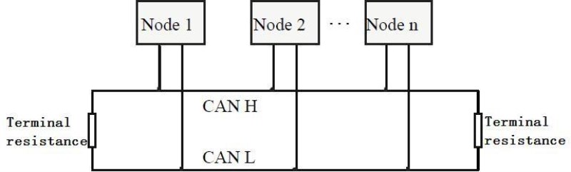
Figure 3.1 CAN-bus network
Note: the CAN-bus cable can use twisted-pair cable, shielded twisted-pair cable. Theory of the maximum communication distance depends on the bus baud rate, Their relationship as shown in the Table 3.1.
Baud rate
|
Distance
|
1 Mbit/s
|
40m
|
500 kbit/s
|
110m
|
250 kbit/s
|
240m
|
125 kbit/s
|
500m
|
50 kbit/s
|
1.3km
|
20 kbit/s
|
3.3km
|
10 kbit/s
|
6.6km
|
5 kbit/s
|
13km
|
Table 3.1 relationship of baud rate and distance
3.3CAN-Bus terminalresistance
In order to improving the communication reliability and eliminating CAN-bus
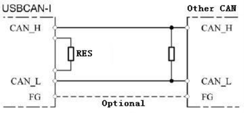
terminal reflection, the two furthest terminal need to connect terminal resistance between CAN_H and CAN_L as shown in figure 3.2. Terminal resistance values determined by the characteristic impedance of the cables. Such as, the characteristic impedance is 120Ω.
Figure 3.2 ECAN Pro connect to other CAN devices
Note: ECAN Pro adapter has none 120Ω terminal resistance inside.
3.4SystemLED
USBCAN-I Pro adapter with one PWR indicator, one SYS indicator, one TX indicator one RX indicator to indicate the adapter status. More functions are shown in table 3.2 and 3.3.
Indicator
|
Colour
|
State
|
PWR
|
Green
|
Power indicator
|
SYS
|
Green
|
System indicator
|
TX
|
Green
|
CAN transmit indicator
|
RX
|
Green
|
CAN receive indicator
|
Table 3.2 USBCAN-I Pro adapter indicator LED
When USBCAN-I Pro adapter power on, PWR and SYS light, indicates the adapter has power supply, the system is initialized; Otherwise, a system power failure or system errors has exist.
When USB-Bus data transfer, SYS indicator will blinking.
When CAN-Bus data transceiver, the corresponding TX or RX will blinking.
Indicator
|
State
|
Meaning
|
PWR
|
ON
|
Power supply normal
|
OFF
|
Power supply error
|
SYS
|
ON
|
Standby mode
|
OFF
|
Initialization error
|
Blinking
|
USB data transmission
|
TX / RX
|
OFF
|
CAN-Bus no data
|
Blinking
|
CAN-Bus data transmission
|
Table 3.3 USBCAN-I Pro adapter LED state
4.ECAN Toolsintroduction
Users can use ECAN Tools software to receive and transmit CAN data. Flexible use of functions can help to more with less.
4.1Start
1.If ECAN Tools has been installed, users can directly run it on thedesktop.
2.
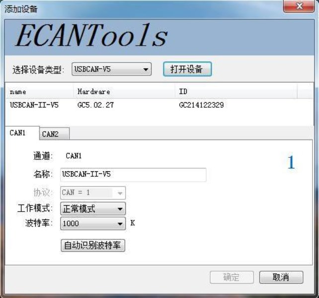
Choose the device type and click "open device", one adapter will shown in the below.
3.Choose work mode. Software provides three kinds of work mode: normal, listen,selftest.
Normal: use this mode to transmit or receive data.
Listen: use this mode to receive data only, and don’t send response or clock. Selftest: use this mode to test if the adapter is working well.
4.Choose baud rate according to the CAN-bus, don’t match will lead to communicationfailed.
If you don’t know the baud rate, you can use “automatic identification of baud rate” function to adapt.
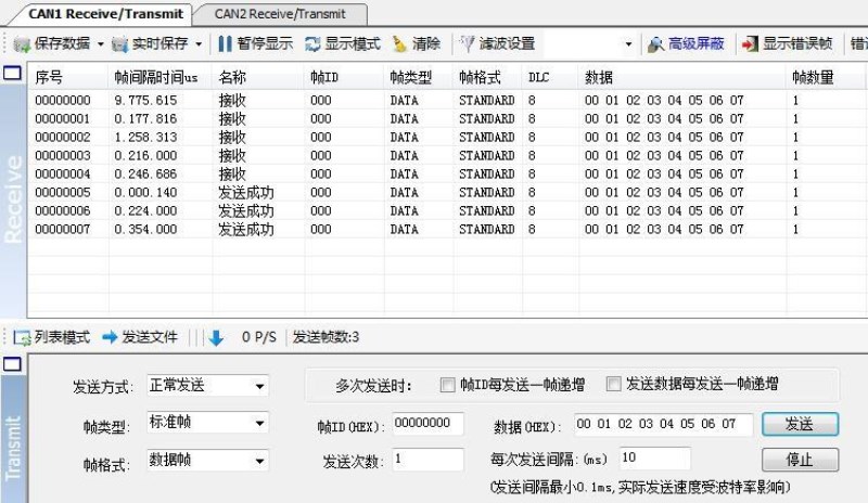
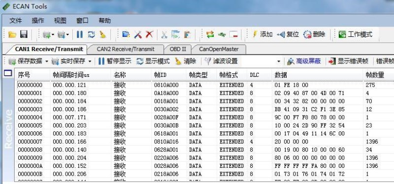
4.2Transmit/Receivedata
Transmitting and receiving is the basic function of ECAN Tools, in this interface, users can directly see the received CAN data, and sent the data to CAN-bus.
4.3CAN-Bus diagnosisfunction
CAN-Bus diagnosis function can detect the bus error frames and bus arbitration
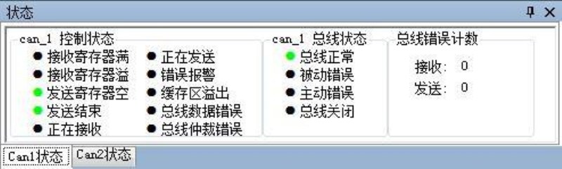
lost.
CAN bus status display: indicate the CAN bus status include: bus normal, passive error, active error、bus hung.
The CAN controller FIFO overflow: message within a certain period of time is too dense, lead to data loss.
The CAN controller error alarm: when many of errors on the bus, error counter exceeds the alarm threshold, and display the error count.
The CAN controller negative error: when many of send or receive errors, lead to the CAN controller into the negative state, and display the error count.
CAN bus controller error: when nodes send or receive errors, error counter value will be accumulate, and can catch the wrong information, such as ACK, CRC error and so on.
4.4Statisticsmode
When receiving data, software can classify these data in ID, data, name, format or type and counting the number of each data.
This function is suitable for large data systems, engineers can easily observe and analyze other data after same data is combined.
4.5

Otherfunctions
Save data: save the receiving list, save format: txt, can, csv and binary.
Display mode: scroll mode and list mode, list mode can classified data together according to the rules.
Filter settings: users can set multi-stage filtering by editing the filter ID. Data mask: masked ID is not displayed.
Error frames: error frames on the bus can be displayed / hidden.
If you want to know more about the software specific function and usage, please see the “ECAN Tools software instructions”document.
5.Secondarydevelopment
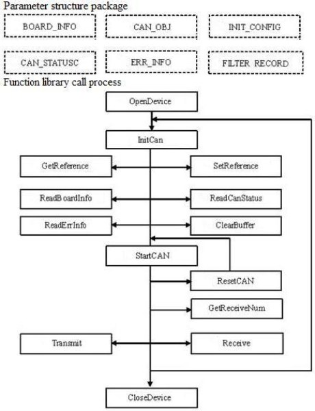
We will provide interface, example and library for secondary development customers. Dll and library named: “ECANVCI.h”, “ECANVCI.lib”, “ECANVCI.dll”. These libraries standards compliant, users can use these in VC, VB and some other programming environment, to use these libraries, please see “ECAN dynamic library manual”and Figure 5.1.
Figure 5.1 Secondary development function call process
6.TechnicalSpecifications
Connection
|
PC
|
USB, type A
|
CAN
|
DB9
|
Interface
|
USB
|
USB2.0 full speed, USB 1.1
|
CAN
|
ISO 11898 standard, support CAN2.0A/B
|
CAN baud rate
|
5Kbit/s~1Mbit/s
|
Isolation
|
1000V, DC-DC
|
CAN terminal resister
|
Integrated, code switch to enable
|
Power
|
Voltage
|
+5V DC (USB port)
|
Current
|
130mA (Max)
|
Environment
|
Temperature
|
-40℃~+85℃
|
Humidness
|
15%~90%RH, without condensation
|
EMC test
|
EN55024:2011-09
EN55022:2011-12
|
IP grade
|
IP 20
|
Basic
|
Dimension
|
55mm * 35mm * 14mm, wire 0.9m.
|
Weight
|
150g
|
Appendix: CAN2.0B frame format
CAN2.0B standard frame
CAN standard frame format is 11 bytes, including two parts: information and data. The first 3 bytes for information.
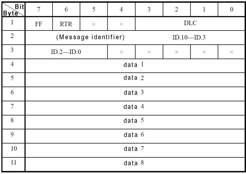
Byte 1 for the frame information. Seventh (FF) means the frame format, in the standard frame, FF = 0; Sixth (RTR) means the type of frame, RTR = 0 means for the data frame, RTR = 1 for remote frame; DLC means the length of the data.
Byte 2, 3 for the message identifier.
Bytes 4~11 for the data of the data frame, remote frame is invalid.
CAN2.0B extended frame
CAN extended frame format is 13 bytes, including two parts: information and data. The first 5 bytes for information.
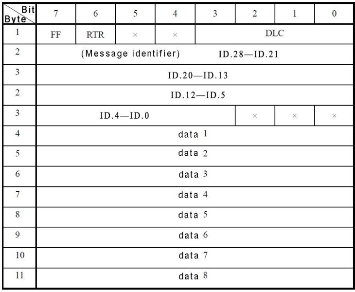
Byte 1 for the frame information. Seventh (FF) means the frame format, in the standard frame, FF = 0; Sixth (RTR) means the type of frame, RTR = 0 means for the data frame, RTR = 1 for remote frame; DLC means the length of the data.
Byte 2~5 for the message identifier.
Bytes 4~11 for the data of the data frame, remote frame is invalid.

