Type:Logic ICs
Condition:New
Supply Voltage:W
Dissipation Power:W
Operating Temperature:W
Model Number:MB6MW
Application:其它
Color classification:6 road acquisition 6 road acquisition +3 road excitation source
32mV ~ + 0 mV differential input signal, using high precision 24 bit AD and the temperature coefficient of the voltage reference 10PPM/ C (max), which can take 6 road weighing sensor, power supply, with 3 10V 1% accuracy of high precision, high stability, isolated signal acquisition, power supply, communication RS485 electrical signal (default 6 road acquisition) :$60.32 6 road acquisition +3 road excitation source price:$69.32 The first chapter product introduction
A. Summary
MB6MW 6Road weighing signal 16 high-precision acquisition module, can collect voltage (0 ~ 32mV), high signal acquisition accuracy.Attached3Road weighing bridge10VExcitation voltage, voltage precision1%The data collected by the weighing signal, through the isolation of RS485 interface output; module using Modbus-RTU communication, can be adapted to PLC, DCS and a variety of configuration software, etc..
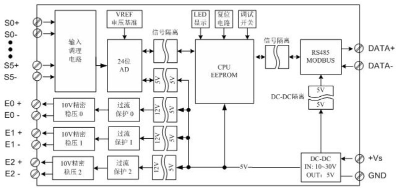
Signal acquisition, CPU and power input, RS485 communication electrical signal isolation, the effective suppression of all kinds of serial mode and common mode interference, to ensure the accuracy of the data, but also to ensure the reliability of the module.
Two. Characteristic
1. Using standard Modbus-RTU protocol.
2. provide3Road weighing bridge10VExcitation voltage, voltage precision1%.
Three High precision signal acquisition: using high precision 24 bit AD and voltage reference, voltage reference temperature coefficient 10PPM/ C (max).
4. Signal acquisition using channel isolation technology.
Five Security: signal acquisition, power supply, RS485 communication electrical signals isolated from each other.
Six Communication protection: RS485 communication signal output interface using overvoltage and over current dual protection.
7. Power polarity protection.
Three. Technical index
| project | parameter |
| AI Signal input | 1Input channel: 6 channel weighing signal acquisition 2Input signal type: + 0 ~ 32mV ThreeAcquisition accuracy: 0.1% 4Resolution: + 32mV/32768 24 was downgraded to 16 bits 5Sampling rate: 6 channels per 300mS acquisition time (50mS a channel)(you can set the collection routes) SixSignal acquisition circuit and CPU isolation voltage protection: 1500V 7. Signal acquisition using channel isolation technology. |
| Excitation voltage | 1. Voltage: 10V precision 3 1% way 2. 3Road 10V output with short time short circuit protection |
| RS485 Communication output | 1Communication protocol: MODBUS-RTU 2Interface type: isolated RS485 communication, the output of the interface using the overvoltage and overcurrent protection 3Baud rate: 1200BPS, 2400bps., 4800bps, 9600bps, 19200bps 38400bps57600bps, 115200bps. 4Check bit: no parity check, parity check 5. setting: module address, baud rate, parity bits can be set by software 6 RS485Circuit and CPU isolation voltage protection: 1500V |
| Module size | A. Separate module size: 104mm*72mm*26mm B. With terminal and guide rail box size: 124mm*72mm*45mm |
| Installation method | Standard DIN guide rail installation (35mm guide rail or high and low track) |
| work environment | Temperature: -10 ~ +55 temperature humidity: 35~85% (not dew) |
| Working power supply | 1Power supply voltage: 10V~30V wide range of power supply, with the power supply polarity protection 2Power consumption: less than 4W |
Four. Product appearance and external wiring diagram
Five. Module indicator lamp and switch function specification
1. POW/SET;Module working status indication
A.Green light: the module works in the running state. B. red light: the module has the configuration parameters have been written, need to re power up.
2. TXD/RXD:Communication status indication
A.The green light flashes: the communication receives the data B. red light flashes: the module is sending data
C.The green light is always on: DATA+ and DATA- on the communication line RS485 line is connected to the reverse or the connection is broken.
Three Module right reset switch
A. When the communication parameters (module address, baud rate, parity bit) do not know or communication parameter misspecification, and can not establish contact module communication, the solution is to reset the communication parameters; we use the clip to hold the reset switch is not open, 5 seconds after the [POW/SET] module of the red indicator lights, release the reset switch, the communication the parameters have been reset, as long as the power supply module after the restart time, the communication parameters of the module has been reset.
B. Communication parameters after reset: Address: 1, baud rate: 9600bps, parity: No.
Six. Typical application wiring diagram
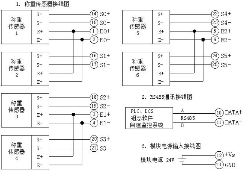
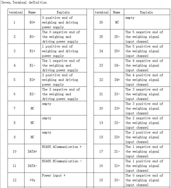
Seven. Terminal definition
| terminal | Name | Explain | | terminal | Name | Explain |
| 1 | E0+ | Weighing 0 positive end of the excitation power supply | 26 | NC | empty |
| 2 | E0- | Weighing drive power 0 negative terminal | 25 | S5- | Weighing signal input channel 5 negative terminal |
| 3 | E1+ | Weighing 1 positive end of the excitation power supply | 24 | S5+ | Weighing signal input channel 5 positive end |
| 4 | E1- | Weighing drive power 1 negative terminal | 23 | S4- | Weighing signal input channel 4 negative terminal |
| 5 | E2+ | Weighing 2 positive end of the excitation power supply | 22 | S4+ | Weighing signal input channel 4 positive end |
| 6 | E2- | Weighing drive power 2 negative terminal | 21 | S3- | Weighing signal input channel 3 negative terminal |
| 7 | NC | empty | 20 | S3+ | Weighing signal input channel 3 positive end |
| 8 | NC | empty | 19 | S2- | Weighing signal input channel 2 negative terminal |
| 9 | NC | empty | 18 | S2+ | Weighing signal input channel 2 positive end |
| 10 | DATA+ | A RS485Communication + | 17 | S1- | Weighing signal input channel 1 negative terminal |
| 11 | DATA- | B RS485Communication - | | 16 | S1+ | Weighing signal input channel 1 positive end |
| 12 | +Vs | Power input + | | 15 | S0- | Weighing signal input channel 0 negative terminal |
| 13 | GND | Power input - | | 14 | S0+ | Weighing signal input channel 0 positive end |
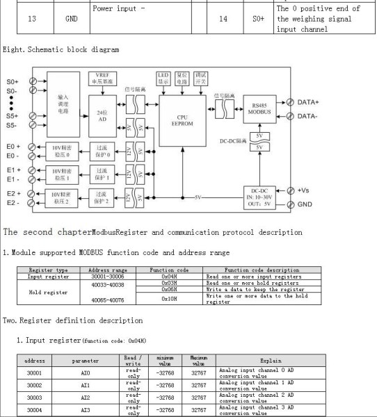
Eight. Principle block diagram
The second chapterModbusRegister and communication protocol
A. Module supports MODBUS function code and address range